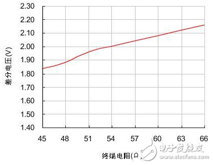
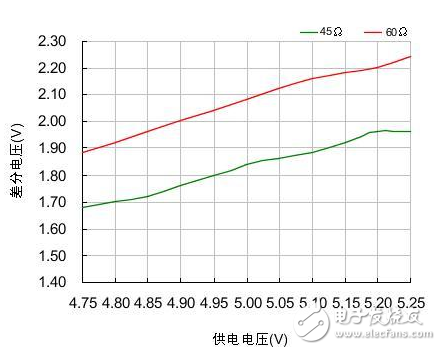
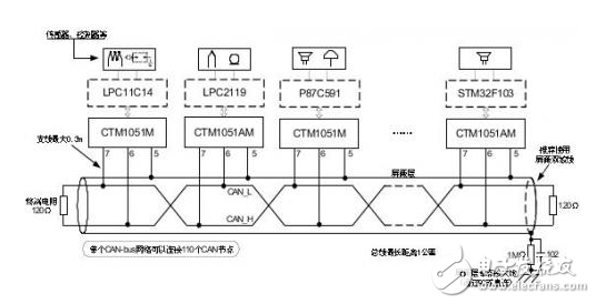
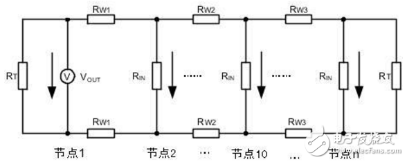
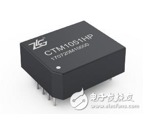
In the CAN-bus circuit design, in theory, the number of nodes supported by the transceiver can be up to 110, but this number is often not achieved in practical applications. Here we talk about how to ensure the reliability and number of nodes in the CAN network through a reasonable CAN-bus bus design. There are many factors affecting the number of bus nodes. In this paper, we discuss the differential voltage amplitude of the receiving node. Only when this precondition is met, we can consider other factors such as parasitic capacitance and parasitic inductance on the signal. 1) CAN node load of the sending node Why consider the CAN interface load? The CAN interface load is the effective resistance value between CANH and CANL. This resistor affects the amplitude of the differential voltage output from the transmitting node. The load resistance RL of each node in the network after networking is close. As shown in Figure 1, we tested the CTM1051M. The output differential voltage amplitude of the small-volume CAN isolation module under different loads. Figure 1 Differential voltage under different loads When the load resistance is increased from 45Ω to 66Ω, the output differential voltage of the node also increases from 1.84V to 2.16V, which is approximately linear. In order to make the output differential voltage of the transmitting node not too low, the actual load resistance of the network should fluctuate within the range tested in Figure 1. We analyze three components of RL: the terminating resistor, the differential input resistance of the bus node, and the effective resistance of the bus itself. Terminal resistance : The terminal resistance needs to be increased at both ends of the bus. When the bus distance is long, the effective resistance of the bus is large and the loss is large. The terminal resistance value can be appropriately increased to reduce the loss of the effective resistance of the bus, such as 150Ω~300Ω. Differential input resistance : The differential input resistance of the transceiver specified in ISO 11898 ranges from 10kΩ to 100kΩ. The differential input resistance of the CTM1051M series transceiver is 19kΩ~52kΩ, which is typically 30kΩ. If we use the most nodes, According to typical values, the differential input resistance of the entire bus will reach 30 kΩ/110=273Ω, which will significantly increase the load of the node when connected in parallel with the termination resistor. Bus effective resistance : use a twisted pair with a small cross-sectional area, its effective resistance reaches several tens of ohms, long-distance communication, the bus will have a great influence on the differential signal, such as the resistance of the commonly used RVS unshielded twisted pair from 8.0Ω /km to 39.0 Ω / km. In severe cases, the level of the receiving point will not reach the recognition range. In addition to the influence of the load resistance, the differential voltage is also affected by the supply voltage. As shown in Figure 2, we tested the differential voltage amplitude of the CTM1051M module under different voltages and different loads. It can be seen that the power supply voltage is increased by 0.5V, and the differential voltage is The amplitude will increase by about 0.3V. Figure 2 Differential voltage at different supply voltages 2) Identification level of the receiving node The receiving node has a certain level identification range. The typical parameters of the CTM1051M CAN interface are shown in Table 1. The node input dominant level should be greater than 0.9V. In ISO 11898, the minimum level of any point on the bus should be greater than 1.2V. When networking, we should make the differential voltage greater than this value. Table 1 CAN interface typical parameters At present, the maximum number of networking nodes of the transceiver is 110. When considering networking, we consider the above resistance parameters to ensure that the differential voltage on the bus is within a reasonable range. Figure 3 shows the networking topology recommended by CTM1051M. We need to consider the bus resistance, termination resistance, transmission point, and receiving point voltage parameters. Draw its equivalent circuit as shown in Figure 4. Figure 3 CTM1051M recommended networking Figure 4 CTM1051M networking equivalent circuit According to the equivalent circuit, the parameters we can adjust are terminal resistance RT, transmitting node voltage VOUT, and bus effective resistance RW. In Figure 4, the RW and RIN of each node are difficult to determine accurately. It is cumbersome to calculate by formula when networking. The simple method is to measure the node voltage at both ends of the bus. If the bus resistance of the network is too large, the loss of the signal from the node 1 to the node n bus will be large. When the differential voltage received by the node n is lower than 1.2V, the termination resistance needs to be increased. In the case of using a surge suppressor, for example, adding a SP00S12 signal surge suppressor between node 1 and node 2 of FIG. 4, the DC equivalent resistance is 9.5 Ω, which can be equivalent to the effective resistance of the bus. When the voltage received by node 1 is too low, the loss due to the surge suppressor can be compensated by reducing the effective resistance of the bus and increasing the termination resistance at node 1. Regardless of the length of the bus network, terminal resistors need to be added at both ends of the network; When the communication distance is long, the terminal resistance value is appropriately increased to reduce the attenuation of the signal by the bus resistance, such as 150 Ω to 300 Ω; Shielded twisted pair is used in places with strong interference, and the shield is grounded at a single point; The differential level of the transceiver CAN interface output will vary with the supply voltage. Make sure that the supply voltage is within the specifications specified in the manual. In outdoor or other complex industrial field environments, in addition to using CAN bus isolation transceivers for signal isolation transmission, it is also necessary to consider how to avoid the impact of harmful signals such as lightning, surge, and overvoltage on the signal transmission system. For such a tough application environment, Zhiyuan Electronics has launched a new generation of high-protection isolation CAN transceiver CTM1051HP, which combines the functions of bus protector on the basis of common isolation transceivers, which can effectively avoid lightning, surge and overvoltage on CAN. The impact of the bus greatly enhances the reliability of the bus. Compared with conventional CAN isolated transceivers, CTM1051HP can be widely used in various high volume requirements or compact products, and can also be used as an optimization scheme for existing CAN isolated transceiver circuits. Usb Cable,Otg Usb Cable,Usb Micro B Cable,Micro Usb Cable Dongguan Swan Electronic Technology Co., Ltd , https://www.swanconnector.com