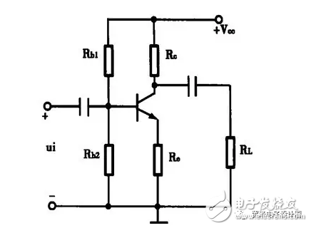
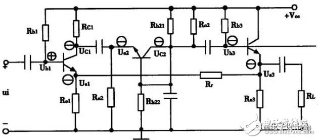
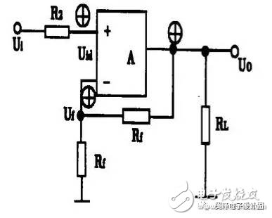
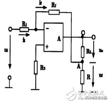
In this paper, the methods of discriminating/retrieving 0 in the analog electronic technology course, such as positive and negative feedback, voltage, current feedback, and series and parallel feedback, are analyzed and compared in detail. Feedback has an extremely wide range of applications in the field of electronic technology. In our electronic equipment, feedback is often used to improve the performance of the circuit, so that the change in the output (voltage or current) of the circuit adversely affects the input circuit, thereby controlling the change of the output, and automatically adjusting the function to achieve The intended purpose. Therefore, feedback has become an important part of the course of analog electronics. However, students often find it difficult to learn this part of the content. Especially for complex circuits, especially when there is not only one kind of feedback in the circuit, it is more difficult to distinguish which part is the feedback. What is the type of feedback? of? This article focuses on this difficulty and talks about the method of discriminating feedback. To determine if there is feedback in a circuit, let the student observe whether there is a jumper circuit component between the input loop and the output loop of the amplifier circuit. If there is such a circuit component, there is feedback; otherwise, there is no feedback. For example, in the circuit shown in Figure 1, Re is present both in the input loop and in the output loop, so Re is the feedback component, indicating that this circuit contains feedback. figure 1 First, the instantaneous polarity is used to determine the instantaneous polarity of the feedback signal, and the instantaneous polarity of the feedback signal is in turn dependent on the polarity of the output signal taken. Master the following principles: (1) For the common emitter circuit, the c pole and the b pole are opposite in phase; for the common base circuit, the c pole and the e pole are in the same phase; for the common collector circuit, the e pole and the b pole are in the same phase. figure 2 For example, the circuit shown in Figure 2 can analyze the circuit according to the above principle. If Ub1 is ©, the phase relationship of each point in the circuit is as follows: Ue3 is ß, and is returned to the emitter of the T1 tube via resistors Rf and e1. Ue1 is ß, that is, the instantaneous polarity of the feedback signal is ß. (2) For the operational amplifier circuit, the inverting input terminal u- and the output uo phase are opposite, and the non-inverting input terminal u+ and the output uo phase are the same. For example, the circuit shown in Figure 3 is judged by the instantaneous polarity method. If the non-inverting input u+ has an instantaneous increment ©, the output uo is ©, and is returned to the inverting input via the resistor Rf, so that u- is ©, that is, the instantaneous polarity of the feedback signal is ©. image 3 Secondly, it is judged whether the circuit introduces positive feedback or negative feedback by comparing the instantaneous polarity of the feedback signal with the input signal. When the input signal and the feedback signal are not introduced at the same node (one of the nodes is the base, the other node is the emitter, or the different input)))), such as differential amplifier circuits, integrated operational amplifier circuits, etc. If the instantaneous polarity is the same, it is negative feedback; if the instantaneous polarities of the two are opposite, it is positive feedback. When the input signal and the feedback signal are introduced from the same node (generally the base), if the instantaneous polarities of the two are the same, they are positive feedback; if the instantaneous polarities of the two are opposite, they are negative feedback. For example, the circuit shown in Figure 2 introduces positive feedback, while the circuit shown in Figure 3 introduces negative feedback. Whether the feedback signal fed back to the input is proportional to the output voltage or proportional to the output current determines whether it is voltage feedback or current feedback, respectively. Note that we judge the voltage feedback or current feedback from the output, instead of judging from the input. The specific judgment method can usually adopt the following three types: (1) Short-circuit the output (ie, let uo = 0), observe whether the circuit still has feedback signal. If the feedback signal disappears in the circuit, it is voltage feedback; otherwise, if the feedback still exists, it is current feedback. For example, in the circuit shown in Figure 3, if uo = 0, then uf = 0, which means that the feedback signal disappears, and this kind of feedback belongs to voltage feedback. (2) It is directly distinguished from the sampling object at the output end. If the sampling object is the output voltage, it is voltage feedback; if the sampling object is the output current, it is current feedback. Here we still take the circuit of Figure 3 as an example. From the output of the circuit, the sampling object is the output voltage uo. Since Rf and R1 form a voltage divider, the feedback voltage uf is part of uo, so it is voltage feedback. (3) In addition to the common grounding line, if the output signal and the feedback signal are taken out from the same point, it is voltage feedback; if the output signal and the feedback signal are taken out from different points, it is current feedback. For the circuit shown in Fig. 4, the feedback signal uf is taken out from the output terminal A, and the output signal UO is taken out from the point O. Since they are taken from different points, they are current feedback. Figure 4 The series feedback and the parallel feedback are distinguished by the way that the feedback signal is compared with the input signal at the input end of the circuit. If the feedback signal is compared with the input signal in the form of voltage, it is series feedback; if the feedback signal and the input signal If the current is compared, it is parallel feedback. Here, we need to emphasize that we are judging whether the series feedback or the parallel feedback is from the input end, instead of judging from the output. The specific judgment method can be as follows: (1) If the feedback signal and the input signal are added and subtracted in the form of voltage in the input loop (ie, the feedback signal is connected in series with the input signal), it is series feedback; if the two are added and subtracted in the form of current (ie, the feedback signal and the input signal) Parallel) is current feedback. For example, in the circuit shown in Figure 3, the feedback signal is subtracted from the input voltage in the form of a voltage, i.e., Uid = ui-uf, and thus is a series feedback. (2) In addition to the common grounding line, if the input signal and the feedback signal are introduced from the same point, it is parallel feedback; if the input signal and the feedback signal are introduced from different points, it is series feedback. For the circuit shown in Figure 3, the feedback signal uf is introduced from the inverting input of the operational amplifier circuit, and the input signal is introduced from the non-inverting input of the operational amplifier circuit. Since not introduced at the same point, the feedback is series feedback. In summary, regarding the relevant judgment of feedback, the following steps can be taken: First, the instantaneous polarity method is used to judge the positive and negative feedback. The second is to use the instantaneous polarity method to confirm which output (voltage or current) the feedback signal is taken from, and then discuss the feedback signal in series (series or parallel). Affects the input of the circuit. Stylus Pen Tip,Stylus Pencil Tip,Carbon Fiber Pen Tip,Carbon Fiber Stylus Pen Tip Shenzhen Ruidian Technology CO., Ltd , https://www.szwisonen.com


