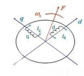
In the operation of the motor, a rotating coordinate system with synchronous rotating speed is established by synchronous rotation of the motor stator and the rotor magnetic field. This rotating coordinate system is a commonly known DQ rotating coordinate system. On this rotating coordinate system, all electrical signals can be described as constants. In order to facilitate the study of motor vector control problems, can the DQ transformation result be directly obtained by the instrument? DQ transform is a decoupling control method, which converts the three-phase winding of the asynchronous motor into an equivalent two-phase winding, and converts the rotating coordinate system into orthogonal stationary coordinates to obtain the voltage and current expressed by the direct current. Relationship. The DQ transformation enables each control quantity to be separately controlled, which can eliminate the influence of harmonic voltage and asymmetric voltage. Due to the application of synchronous rotation coordinate transformation, the separation of fundamental wave and harmonic is easy to realize. Since the main magnetic flux of the DC motor is basically uniquely determined by the excitation current of the field winding, this is the fundamental reason why the mathematical model of the DC motor and its control system are relatively simple. Analysis and control can be greatly simplified if the physical model of the AC motor can be equivalently transformed into a DC-like mode. The coordinate transformation is carried out according to this idea. AC motor three-phase symmetrical static windings A, B, C, through the three-phase balanced sinusoidal current, the resulting synthetic magnetomotive force is the rotating magnetomotive force F, which is sinusoidal in space, with synchronous speed ws (ie The angular frequency of the current is rotated along the phase sequence of the ABC. Such a physical model is depicted in the figure below. Rotating magnetomotive force does not necessarily have to be three-phase non-existent. In addition to single-phase, any symmetrical multi-phase windings such as two-phase, three-phase, four-phase, etc. can generate rotating magnetic flux through balanced multi-phase current. The momentum is of course the simplest of the two phases. In Fig. 2, two-phase stationary windings a and b are depicted which are 90° out of phase with each other, and a two-phase balanced alternating current with a time difference of 90°, which also produces a rotational magnetomotive force F. When the magnitudes and rotational speeds of the two rotational magnetomotive forces of Figures 1 and 2 are equal, it is considered that the two-phase winding of Figure 2 is equivalent to the three-phase winding of Figure 1. Figure 3 shows two windings d and q of equal and perpendicular to each other, with DC currents id and iq respectively, resulting in a resultant magnetomotive force F whose position is fixed relative to the winding. If the entire core including the two windings is rotated at a synchronous speed, the magnetomotive force F naturally rotates to become a rotating magnetomotive force. By controlling the magnitude and rotational speed of this rotational magnetomotive force to be the same as the magnetomotive force in Figures 1 and 2, the rotating DC winding is equivalent to the two sets of fixed AC windings. Figure 3 Rotating DC winding It can be seen that the three-phase alternating current winding of FIG. 1, the two-phase alternating current winding of FIG. 2, and the integrally rotating direct current winding of FIG. 3 are equivalent to each other with the same rotational magnetomotive force as a criterion. In other words, iA, iB, iC in the three-phase coordinate system, ia, ib in the two-phase coordinate system and DC id, iq in the rotating two-phase coordinate system are equivalent, they can produce the same rotation. Magnetomotive force. The theory of motor coordinate transformation has been widely used in the field of electrical engineering. It is widely used not only in motor control and transient analysis, but also in power system fault analysis and grid power quality detection and control. Motor coordinate transformation theory The main applications are as follows. 1, motor control 2. Analysis of transient operation of the motor 3, motor fault diagnosis DQ conversion is widely used in motor testing. As long as the rotor position can be accurately obtained and the current of the three-phase signal can be accurately measured, a real-time algorithm operation can be realized by using a high-speed FPGA in parallel, and the three-phase coordinate system of the stationary stator relative to the stationary stator can be converted into a two-phase coordinate system of the stationary stator by a clark transform. The corresponding transformed outputs Iα and Iβ are output, and then the park transform is used to convert the two-phase coordinate system that is stationary relative to the stator into a two-phase coordinate system that is stationary with respect to the rotor to calculate ID and IQ. The motor control process is an inverse transformation process. First, the excitation current and the torque current are set, and then converted to two phases that are stationary relative to the stator, and then converted to three phases that are stationary relative to the stator, thereby realizing control of the motor. At present, ZLG Zhiyuan Electronics is planning to implement this DQ conversion function in the power analyzer, which can provide reference for motor control. The motor control process can design and control the motor control by comparing the set value with the result of the power analyzer test. , algorithm optimization, etc. (Source: ZLG Zhiyuan Electronics) Lens Hood,Lens Accessories,Camera Lens Hood,Camera Hood Shaoxing Shangyu Kenuo Photographic Equipment Factory , https://www.kernelphoto.com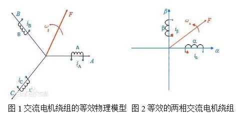
Application of DQ coordinate transformation
Test Methods