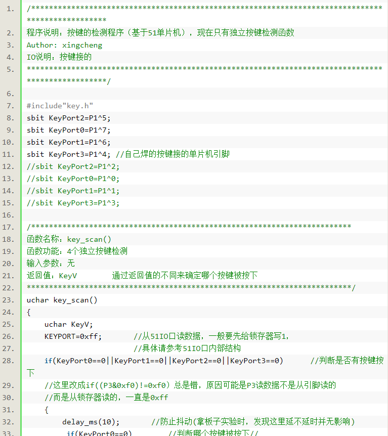
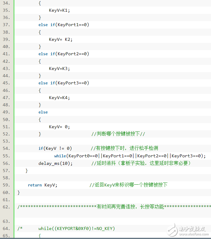
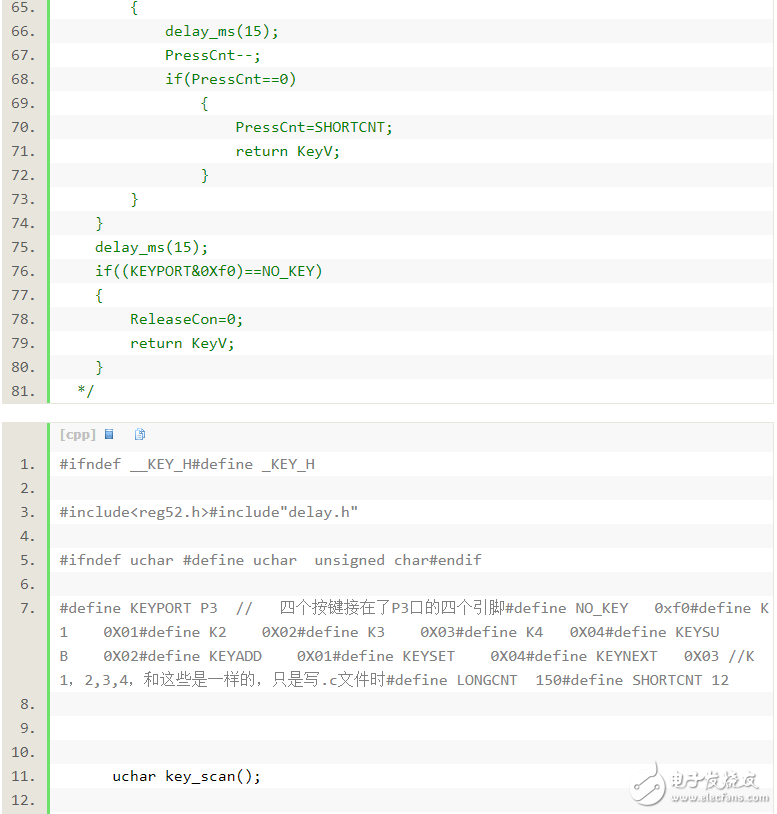
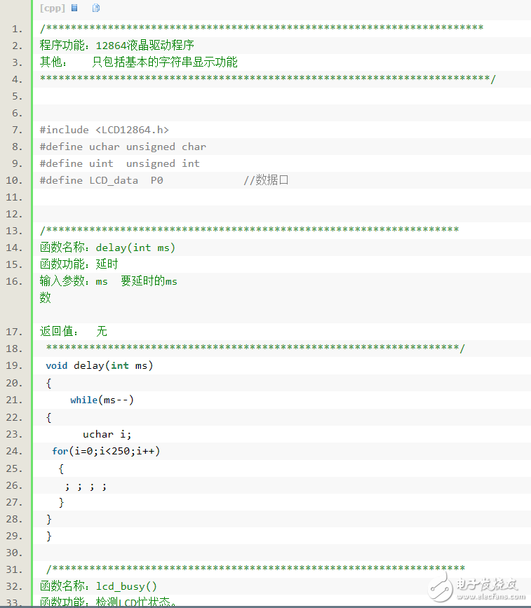
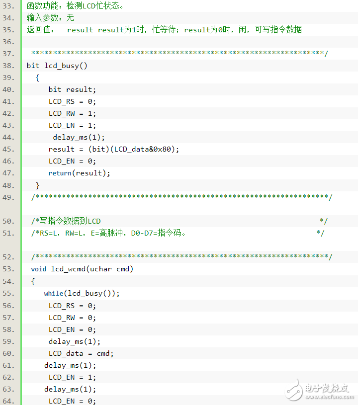
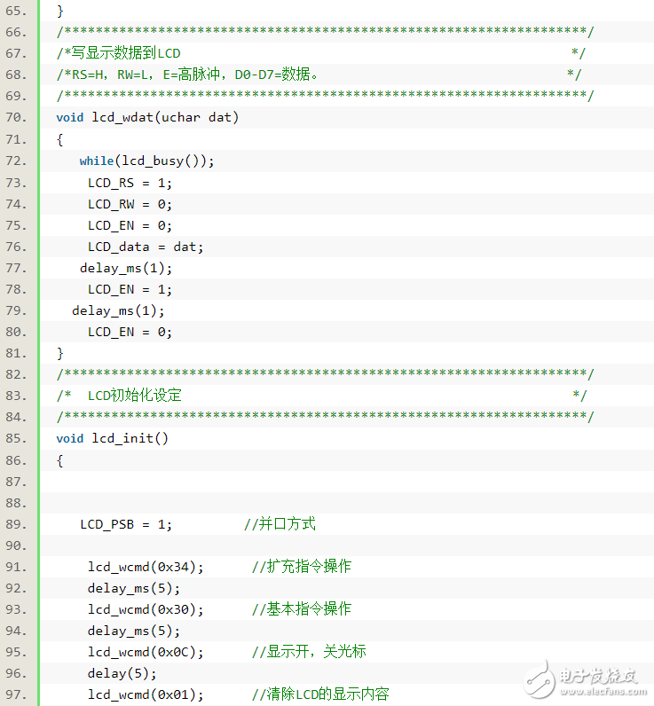
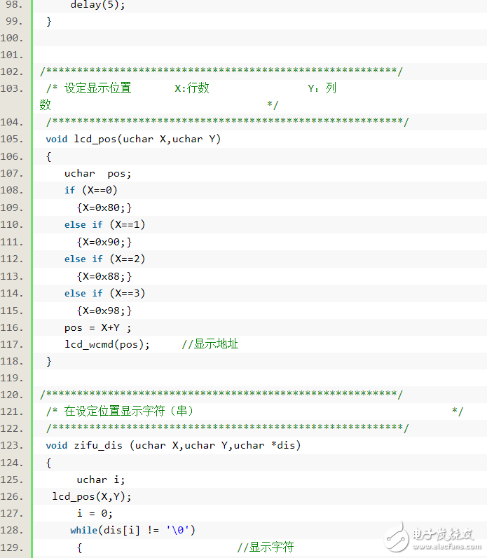
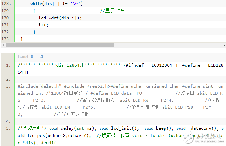
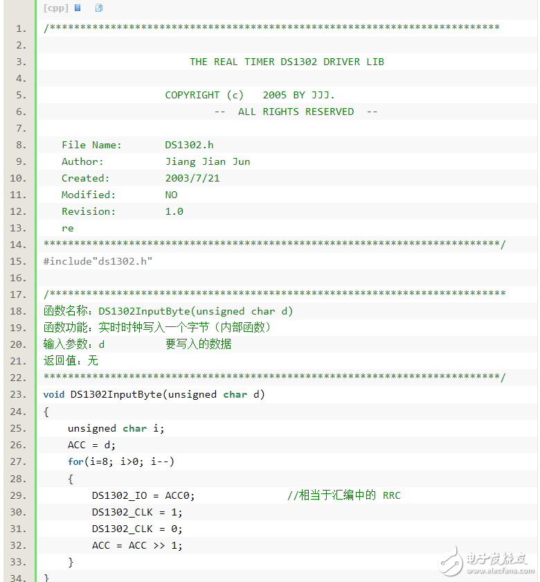
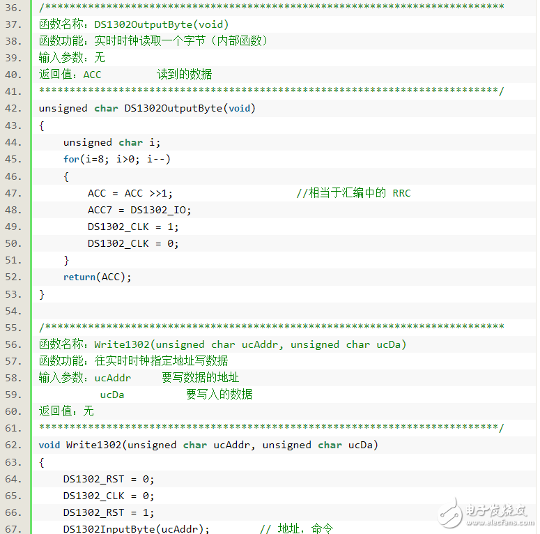
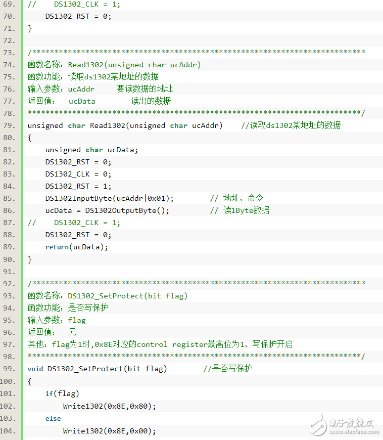
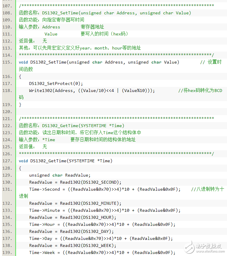
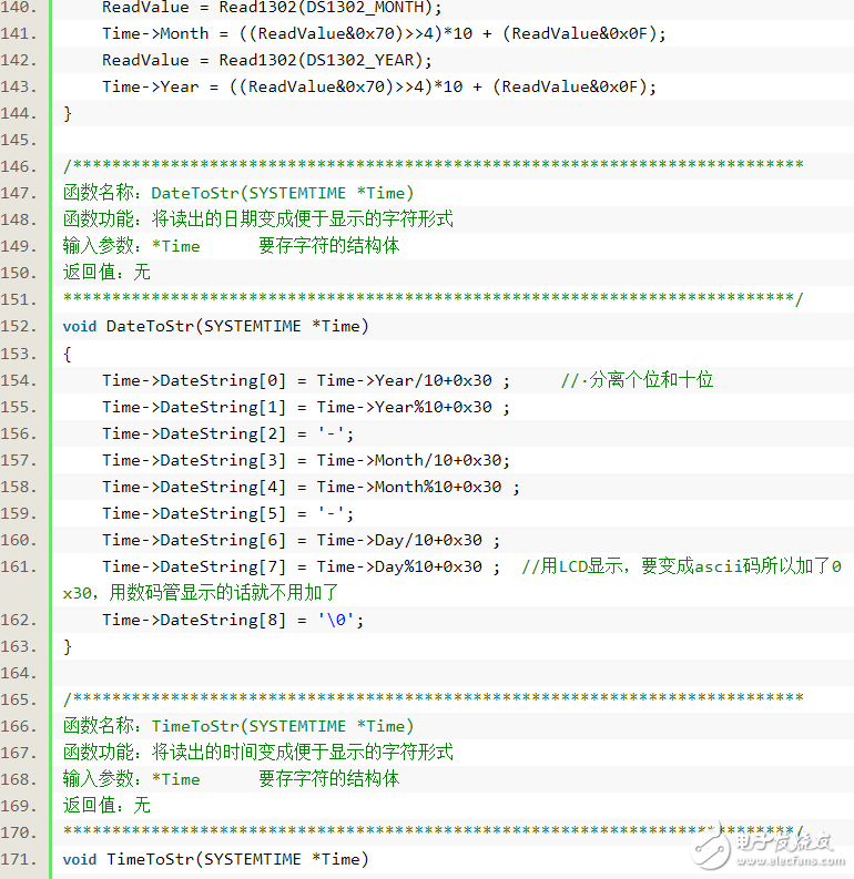
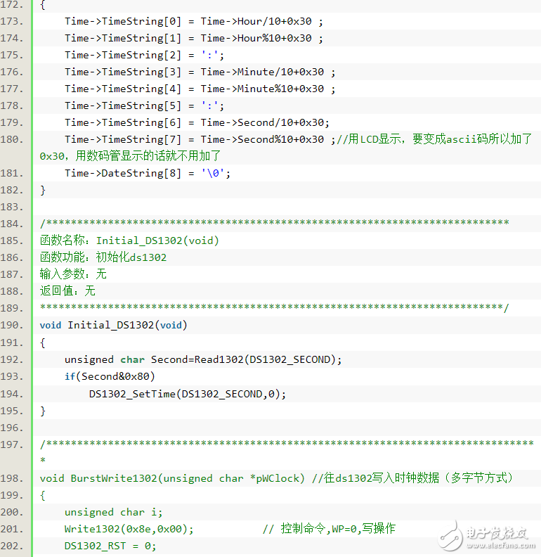
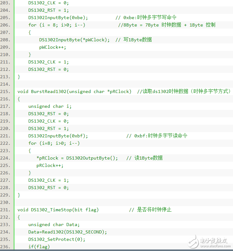
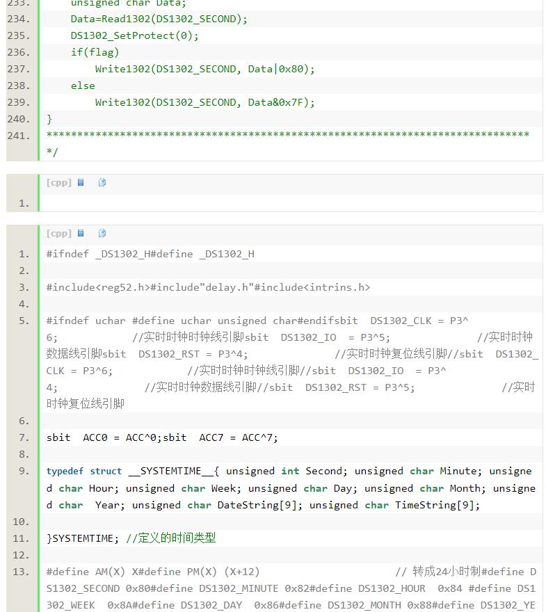
First of all, let me talk about the things I use, the hardware (the circuit is to take the universal board welding): a 51 single-chip, a 12864 LCD, a ds1302 clock chip, four buttons. There are still some capacitors, resistors, crystal oscillators or something, let's talk about it later. The main thing is so much. Let's briefly talk about the function of the buttons, assuming that the buttons are k1, k2, k3, k4. First, the lcd main interface is the current date and time displayed and the time of the four-way alarm clock. The figure. When k1, k2, k3, k4 are initially pressed, the corresponding functions are k1: enter time setting mode; k2: enter date setting mode; k3: enter alarm setting mode; k4: enter stopwatch counting mode. After entering different modes, all four buttons have new functions. First, k4 is always exiting, that is, exiting to the first four modes. K1, k2, k3 are the same function for the date and time setting mode. k1: value plus 1, k2: value minus 1, k3: whether the hour or minute or the year or month is changed. For the alarm mode, k1: value plus 1, k2: change the hour or minute, k3: change the alarm is the first few alarms. For the stopwatch mode, k1: the first press is to start counting, and then press to record how many seconds are currently, up to 9 times. K2: Pause/Start, k3: Recount. A little bit flustered, simply saying that there are two cycles. If you still don't understand it, you can look at the code below. How to say this part, it is simple and simple. But one of them has not passed yet. At the very beginning, I intend to solder a download circuit on top of it, and the result is always not going to the program. This part is a digression, but I still want to talk about it briefly. At first, I was going to use the CH340 chip to directly transfer us to uart. As a result, the chip was bought and found to be not directly inserted. It’s too much trouble to rot the board yourself. Finally, I plan to use the usb to turn the nine-pin serial port to convert to rs232 level, and then use max232 to convert to uart level. According to the circuit diagram, the results of the welding, the results did not come out as I expected, it is impossible to successfully enter the program. Just look for the problem, find it, find it. It seems that one is found, is the program under 51 not a power-off process in power-off? I did this, but there seems to be a problem. The power that is broken should be only the power of the microcontroller, not the power of max232. So I changed the circuit again, but it still didn't work. Forget it, I will understand it later and talk about it. The rest should not be too difficult, looking for a 51 minimum system schematic according to the welding, there is not much problem. law Yes, there are a few small points, let me mention it. The P0 port of 51 is equivalent to the open circuit of the collector, remember to connect the pull-up resistor. When the LCD screen guides the program, if you don't display anything at first, remember to adjust the backlight by adjusting the potentiometer connected to the 3-pin. 1. Button detection This part seems to me that there is no big article at the beginning, and there is nothing worth to write. A little basic person can write the program in a few minutes. However, when I was writing, I realized that I didn’t know too much and I had to learn too much. The most common two functions of the IO port of the MCU, input and output. Remember that when you learn stm32, the input and output of the IO port is defined at the very beginning. That is to say, the IO port can only have one function at the same time, and it is impossible to input the output again. But what about 51? Let me force, there is no definition of whether the IO port is input or output anywhere, including the startup file. This makes me very depressed, I will not let an IO port output a high level, you can also read the input from the IO port, so that should not always read is the high level of my output. Until I studied a wave of internal circuits of the 51IO port, I realized the mystery. Here is the simplest internal structure of the P1 port. A person with a little electric basis can probably understand. I won't talk about it specifically. As can be seen from the above figure, in order to correctly read the external information from the pin, the FET must be turned off first, so that the state of the pin is determined by the external input information. To do this, you must write a l to the port before doing the pin read. An input/output port having such an operation characteristic is called a quasi-bidirectional I/O port. The P51, P2, and P3 of the 8051 MCU are quasi-bidirectional ports. Since the output of the P0 port has a three-state function, the port line is already in a high-impedance state before input, and it is not necessary to write the l first before performing the read operation. After understanding the internal structure of the IO port. I will go directly to the program and study it slowly. Don't entangle the comments and unused parts. 3 2.lcd12864 This is really nothing to say. Just remember to adjust the potentiometer to adjust the backlight. By the way, there is a good pit. I don't know if you have a solution. That is, the cursor (the one that flashes and flashes) is moved by two words and two words. On the program. 3.ds1302 clock Directly to the program, the corresponding information can be found online. The main program modules are basically ready here. The complete program I compressed and uploaded to the resource, (no way to earn points, understand and understand), in fact, to this step, everyone should write the complete program is not a problem. Let's talk about other things. When using keil software, always report such an error *** ERROR L107: ADDRESS SPACE OVERFLOW. It is also a multi-party search to find the problem. That is, the variable we defined is defined in the RAM of 51, and only 256 or 128 bytes are stored for the variable (see model). Here, I see online to add idata in front of the variable, but it does not work. Still try to save RAM. Read-only array definitions are preceded by code, and global variables are as small as possible. If you can't, you can only change the MCU. After all, 51 is a single-chip device with few resources, which is not suitable for some big projects. Finally add a picture 600 Puffs Disposable ecig Geek Bar Vape have a completely enclosed design, reducing the need for charging and replacing cartridges. The no-charge design also reduces the occurrence of faults. It is understood that with rechargeable e-cigarettes, each cartridge needs to be charged at least once and the battery efficiency is extremely low, while the design of disposable ecig can solve this problem very well. 600 Puff E-Cigarette,600 Puff E-Cigarette For Sale,Best 600 Puff E-Cigarette,Best 600 Puff E-Cigarette For Sale Shenzhen E-wisdom Network Technology Co., Ltd. , https://www.healthy-cigarettes.com