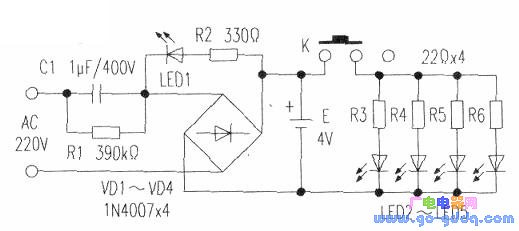
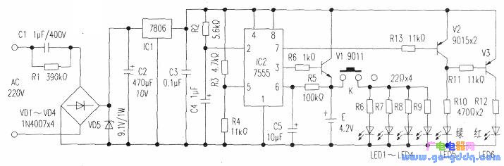
Now, the flashlights that everyone uses are made of LED tubes. The tungsten filament bulbs that were used before have disappeared. The circuit inside the rechargeable LED flashlight is shown below. It uses the capacitor step-down method to charge the battery E, that is, the 220V voltage is stepped down by the capacitor Cl, and the bridge rectifier of VDl~VD4 is used to charge the 4V lead-acid battery. In use, when the switch K is closed, the 4V voltage is passed through the four current limiting resistors R3 to R6, and then applied to the white LEDs LED1 to LED4 to cause the LED tube to emit light (the operating current is about 100 mA to 120 mA). The LED flashlight is the most convenient and economical. However, this flashlight has a fatal weakness, that is, the internal battery will fail after a certain number of charges, that is, the battery will not be charged. If you want to buy a new battery is not economical, you have to discard it. Here is a method of replacing the failed lead-acid battery in the flashlight with a lithium battery that has been removed by a mobile phone, so that the flashlight can be brought back to life. First, the working principle The lithium battery that has been retracted by the mobile phone has reduced its capacity, but it is still possible to use it on the flashlight (that is, its capacity is only 40% to 50% of the original). However, the charging conditions of lithium batteries are required to be high. For example, its charging voltage should not exceed 4.2V (if there is a risk of bursting if it exceeds). At the same time, its minimum discharge voltage also has certain requirements. Fortunately, the retreating 铿 battery is equipped with a protection circuit, but for the sake of safety, an automatic power-off circuit and a work indicating circuit are also designed. Use the mobile phone lithium battery as the power supply circuit diagram, as shown below. It also uses the original capacitor step-down circuit and white LED tube circuit. However, the capacity of the step-down capacitor is increased (1.5 μF). After the AC 220V step-down voltage is regulated by VD1 ~ VD4 rectification and voltage regulator VD5 voltage stabilizes the voltage at about 9V. After the voltage regulation of IC1, a stable voltage of 6V is obtained. IC2 is a CMOS type time base circuit (model number is 7555). This circuit is more economical than the 555 time base circuit and has a high output voltage. It is composed of a lithium battery charging automatic power-off circuit. The 5 pin of IC2 is the control terminal. It sets the reference voltage (here set to 4.2V) through the voltage dividing resistors R3 and R4, which is the termination voltage of the lithium battery. When the power is turned on, the 6V voltage output from IC1 charges capacitor C4 through R2. When charging starts, the voltage at pin 2 of IC2 is 0V, and the pin at output 3 is high. Thus, the transistor V1 is turned on to charge the lithium battery E (the current is controlled by the transistor V1 in the range of 50 mA to 80 mA). As the voltage of the charged lithium battery continues to rise, when the voltage reaches 4.2V, the voltage of the 6 pin of IC2 also reaches 4.2V, so that the 3 pin outputs a low level, and stops charging the lithium battery. The purpose of capacitor C5 is to avoid interference with the 6-pin voltage at the beginning of charging. The indicating circuit is composed of transistors V2, V3, LED5 and LED6. When the circuit is in the charging state, pin 7 of IC2 is turned off. The 6V voltage passes through the emitter junction of V3, Rll, R10 and LED5, forming the base current. However, this base current is not sufficient to cause the LED 5 to emit light, and the red tube of the LED 6 emits light. After stopping charging, IC2's 3 pin is low level, 6V voltage is passed through V2's emitter junction, R13, and then added to IC2's 7 pin (7 pin is turned on), so that V2 is turned on, V3 is turned off, and LED5 is green. Glowing. Second, the circuit components requirements and production methods In the circuit, Cl uses a 1.5μF/400V polyester capacitor. The voltage regulator VD5 uses 1W and 9.1V. Capacitor C5 uses a 5μF to 10μF tantalum capacitor with a small leakage current. The transistor V1 uses 9011 (β is in the range of 80 to 100), and V2 and V3 are 9015 (β is in the range of 200 to 250). The original indicator light tube is changed to two colors φ3 (LED5 and LED6). Battery E uses a mobile phone battery of 500mAH to l000mAH and 3.7V. There are no special requirements for other components. At the time of production, the additional circuit is made on a small circuit board. After the circuit is soldered correctly, the AC 220V voltage is connected, the circuit works normally and the battery is charged, then the red LED tube emits light. The output of IC1 should be 6V. Then use a multimeter to measure the battery voltage: When the battery voltage reaches 4.2V, the charging should be terminated and the green LED will be on. If the battery termination voltage value is different, you can change the size of R4 to adjust. During installation, due to the small space inside the flashlight, it is required to saw the metal part of the 7806 voltage regulator block. The capacitor C1 can re-weld a 0.47μF/400V polypropylene capacitor at the original 1μF capacitor position. Finally, the circuit board and the battery are stacked (with a thin plastic piece in the middle) and then placed in the original lead-acid battery position. Considering that the Zener diode VD5 is more hot when the battery is not charged, it can be connected in parallel with two tubes of the same type. Timer,Electronic Timer, Waterproof Timer, Countdown Timer NINGBO COWELL ELECTRONICS & TECHNOLOGY CO., LTD , https://www.cowellsocket.com