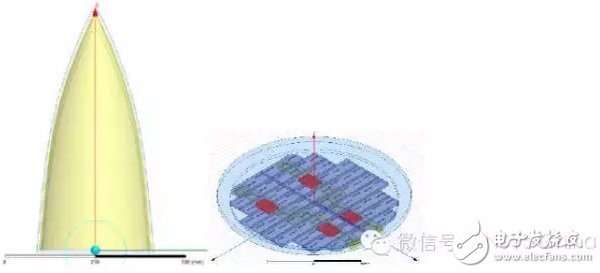
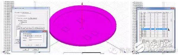
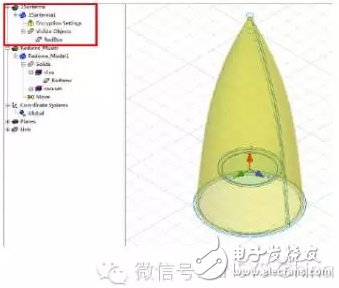
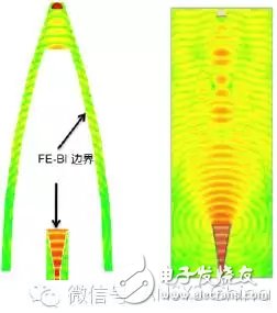
The radome is a dielectric casing used to protect the antenna, so that the antenna can avoid damage caused by various harsh environmental conditions, but the presence of the radome also affects the electrical performance of the antenna, including radiation pattern, power transmission loss, Aiming errors, etc. With the popularity of ANSYS HFSS software in the design of antenna feeder systems, the simulation-based design flow for antennas and their front-end feed networks has matured. Advanced design methods also promote the development of RF modules in the direction of higher performance and higher integration. With the continuous improvement of the antenna index, the electromagnetic design of the radome, especially the integrated design and co-simulation of the radome and the antenna or antenna array has become an urgent problem to be solved. The radome is an important part of a complex antenna system, and its electromagnetic design is also quite difficult. Many radomes are a mixture of large size and complex materials. At the same time, when the internal is a waveguide crack antenna array, the rotation angle of the antenna needs to be considered, and the aiming error and the aiming error slope caused by the rotation have high requirements for calculation accuracy. It is necessary to use the full-wave simulation technology to perform an overall accurate simulation of the antenna array radome. The large-scale calculations and large simulation tasks generated by it need to be realized by advanced algorithms and parallel solving techniques. In the usual R&D process, the radome and the antenna or antenna array are often developed by different design teams. In the study of the electrical performance of the radome, it is necessary to integrate the antenna or the antenna array with the radome to obtain more precise. And reliable results, because only in this way can complex near-field effects be taken into account. Therefore, the safe transfer of the simulation model has become a problem that must be solved in the actual development process. Figure: radome and waveguide crack array model The ever-improving 3D Component function in HFSS can save the HFSS simulation model as a 3D Component. This component contains all the settings and information needed for HFSS simulation, including 3D structure, material properties, ports, boundary conditions, meshing. Modes, hybrid algorithm settings, etc., can be used directly for new simulations. In the latest version of HFSS 2016, 3D Component adds a new encryption function, in addition to the security of the password protection model, but also hides the structural details of the model, in the eyes of 3D Component users, like a black box. However, all the performance of the complete model can be obtained through simulation, which further ensures the security of model delivery and protects intellectual property. Figure: 3D Component encryption settings, you can choose the structure you want to hide or display In this test case, we hide all the internal structural details of the waveguide crack array, allowing only the outermost air box to be displayed. In the new project file, we insert the 3D Component files of the well-preserved radome and waveguide crack array, and adjust the relative position. Only a few simple operations are needed to complete the integrated model of the radome and the antenna array. It is set up and no further material properties, ports, boundary conditions, etc. are required, as all of these settings have been brought to the new model with the 3D Component. Since the 3D Component of the waveguide crack array has been encrypted and hides internal details, only the unhidden air box can be seen in the assembled model. The basic information of the model is as follows: Radome: single layer dielectric cover, height 650mm, bottom diameter 320mm, thickness about 2.5mm; Waveguide slot array: round aperture, diameter 185mm, four-port feed; Working frequency band: 15GHz. Figure: 3D Component assembled integrated model, the internal details of the antenna array are completely hidden The large size media radome in the simulation algorithm, HFSS FEM-IE hybrid algorithm is the best choice. The high-frequency progressive algorithm represented by PO and UTD can only be effective for the large-scale problem of pure metal. It is impossible to simulate the radome with medium structure, and the multiple reflection of the electromagnetic beam leads to a complicated path inside the radome. The traditional ray-based theory The high-frequency algorithm is difficult to deal with; the simple method of moments is difficult to generate the Green's function when solving the multi-layer dielectric structure, and it is difficult to solve the cavity problem of the dielectric structure with arbitrary three-dimensional surface and the waveguide crack array; The method is very good at solving arbitrary three-dimensional structures and antenna array problems, but the huge computational complexity caused by the large solution space will reduce the simulation efficiency. Compared with the single full-wave finite element or moment method, the hybrid algorithm of HFSS mixed with finite element and integral equations can reduce the solution space size, reduce the computation and reduce the consumption of time domain resources. In the HFSS, the FE-BI boundary technique is used, and the finite element algorithm is used inside the boundary. The boundary surface is integrated equation algorithm. A large amount of air region between the radome and the antenna can be removed from the finite element solution domain and can be completely conformal with the antenna. . Figure: FE-BI boundary (left) can significantly reduce solution space compared to finite element radiation boundary (right) We can follow customers' drawings or design to make Customized wire
harness for various industries: game machine, ATM, POS machine, etc.
Customized
wire assembly with AVL components from original manufactures. Also
harness with local equivalent componets are workable with short L/T and
competitive price, also flexible MOQ.
Medical Wire Assemblies,Medical Alligator Clip Cable,Medical Cable Assembly,Medical Wire Harness,Medical Cable ETOP WIREHARNESS LIMITED , https://www.oemwireharness.com