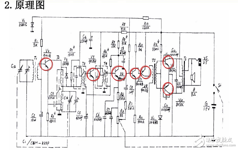
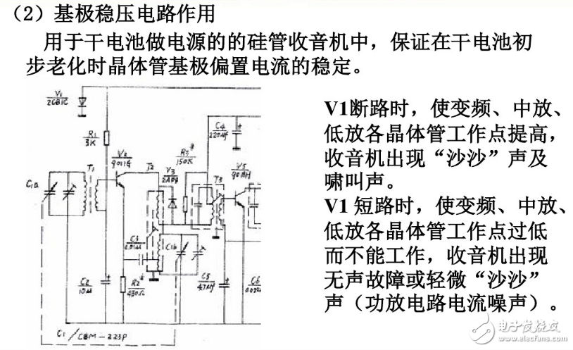
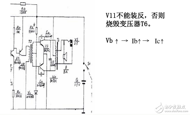
Knowing where and what role the electronic circuit schematics you read is useful for getting to know the working principle of the circuit, the functions and performance indicators of each part. You can see the following picture: This is a typical full-band radio circuit diagram. Its purpose is to send the received high-frequency signal through the input circuit and an oscillating current generated by the radio itself into the frequency conversion tube for "mixing" (mixing). After mixing, a frequency conversion stage load loop (frequency selection) is generated. The new frequency (difference frequency), that is, the intermediate frequency (465kHz), then passes through the mid-amplifier, detector, low-amplifier, and power amplifier to drive the speaker to sound. Of course, it is also required to adjust the oscillation frequency (f vibration-f letter = 465kHz), and can adjust the volume. Refers to finding the path of signal flow. usually. The input is on the left and the output is on the right (facing the circuit diagram). The hub of signal transmission is active devices, so you can find them according to their connection relationship. Looking from left to right, the active components of this circuit are BG1 (frequency conversion tube), BG2 and BG3 (middle amplifier tube), BG4 and BG5 (low amplifier tube), BG6 and BG7 (power amplifier tube), so it can be roughly inferred The signal is input from the base of the BG1, oscillates and mixes to produce an intermediate frequency signal, and then passes through a two-stage intermediate amplifier, and then the intermediate frequency signal is converted into an audio signal by the detector, and finally sent to the speaker after low amplifier and power amplifier. , The signal path is roughly found. After the access is found. The main components of the circuit are also out. Along the main path of the signal. According to each basic unit circuit or functional circuit, the schematic diagram is divided into several parts with a single function. The degree of division is related to the reader's mastery of circuit types and experience. According to the above-mentioned path, it can be clearly seen that the whole circuit can be divided into three parts by BZ1 and D1 (2AP9) respectively, which we call the frequency conversion stage, the intermediate amplifier stage (including the detection stage) and the low power amplifier stage (output). After dividing into unit circuits, according to existing knowledge. Qualitative analysis of the working principle and function of each unit circuit. 1. Input circuit and frequency conversion stage The task of this part is to convert the received high-frequency signals of various frequencies into a fixed intermediate frequency (465kHz) signal and send it to the intermediate amplifier. It involves two tuning loops: One is the input tuning circuit, and the other is the local oscillation circuit. The input tuning circuit selects the inductive coupling form (magnet coil B1), and the local oscillation circuit selects the transformer coupling oscillation form (B2). Because the double-connected variable capacitors (C1a, C1b) can coaxially tune the frequency of the input circuit and the local oscillator circuit, the frequency difference between the two can be kept unchanged. The local oscillator and frequency mixing of the frequency conversion stage circuit are served by a triode BG1. Due to the amplification and nonlinear characteristics of the triode, the frequency conversion effect can be obtained. It can be seen from the figure below: This is a frequency conversion stage in which the oscillating voltage is injected from the emitter and the signal is injected from the base. The two signals are mixed in the transistor at the same time, and through the non-linear effect of the transistor and then the frequency selection effect of the intermediate frequency transformer BZ1, an intermediate frequency amplitude modulation wave with a frequency of f vibration-f signal = 465kHz is selected and sent to the intermediate amplifier. Intermediate level (including detector) 1) IF amplifier stage The intermediate amplifier stage uses a two-stage single tuning intermediate frequency amplifier. The intermediate frequency amplitude modulation wave signal output by the frequency conversion stage is sent from the BZ1 secondary to the base of BG2 for amplification, and the amplified intermediate frequency signal is sent to the base of BG3, and the amplified signal is output by the BZ3 secondary. All three intermediate frequency transformers should be adjusted accurately at 465kHz. The characteristic of the intermediate frequency amplifier stage is to use the parallel LC tuning loop as the load. The reason is: the parallel resonant circuit, like the series resonant circuit, can resonate a signal of a certain frequency, but the difference is at resonance. The impedance of the series resonant circuit is very small, the current in the circuit is very large, the smaller the impedance, the higher the Q value; while the parallel resonant circuit is at resonance, the impedance is very large, and the voltage at both ends of the loop is very high. The smaller the value, the higher the Q value. Because the intermediate frequency amplifier uses a parallel circuit resonant at 465kHz as the load. Therefore, after using the intermediate frequency amplifier, the selectivity of the whole machine is greatly improved. 2) Detection stage In a superheterodyne radio, although the high-frequency signal is converted into an intermediate frequency signal through the frequency conversion stage, the intermediate frequency signal is still an amplitude modulation signal. Therefore, it is necessary to rely on the detector to turn the intermediate frequency signal into a low frequency signal (audio signal). The intermediate frequency signal sent from the BZ3 secondary to the detector diode is cut off by the negative half cycle and becomes a positive half cycle amplitude modulated pulse signal, and then select the appropriate capacitance After filtering out the residual intermediate frequency signal, the audio component can be taken out and sent to the low amplifier stage. The DC component of the audio pulse signal output by the detector is filtered by R7 and C13 as the automatic gain (AGC) voltage. Feed into the base of the first intermediate amplifier tube BG2 to achieve the purpose of automatically stabilizing the intermediate amplifier gain. Low power amplifier level 1) The intermediate frequency signal output from the detection stage by the low-amp circuit. It also needs to be amplified and then sent to the speakers. In order to obtain a larger gain. Usually the pre-stage low-frequency amplification chooses BG4 and BG5 two stages. BG4 and BG5 adopt direct coupling mode. The bias voltage of the BG4 base is taken from the voltage on the BG5 emitter resistor R14, so there is a strong negative feedback to the DC operating point, which is beneficial to stabilize the operating point. The excitation between the low amplifier stage and the power amplifier stage uses a transformer (B3) coupling method. 2) Power amplifier stage The power amplifier stage uses two NPN tubes of the same type to form an OTL symmetrical circuit in BG6 and BG7. The two tubes work in turn to obtain a complete sine wave voltage on the load (speaker). R16 and R17 form the bias circuit of BG6, and R18 and R19 form the bias circuit of BG7. R15, C12, C16 form the power filter circuit, and the capacitor C19 is used to improve the sound quality. UV Screen Protector,UV Curing Machine,UV Curing Screen Protector Shenzhen Jianjiantong Technology Co., Ltd. , https://www.hydrogelprotectivefilm.com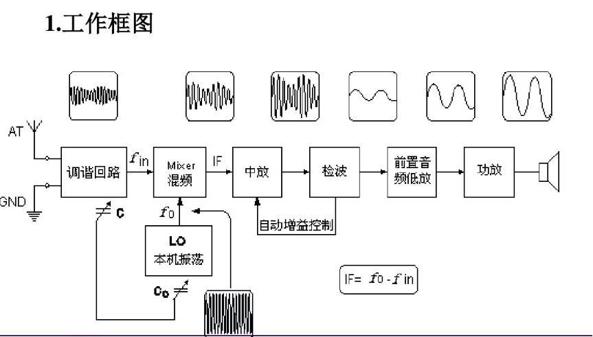

Circuit diagram analysis of full band radio
Understand the purpose