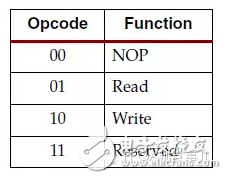
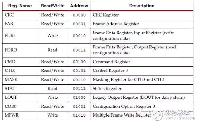
The SELECTMAP32 interface is used to configure and read back the V5 series SRAM type FPGA produced by XILINX. The configured FPGA is hereinafter referred to as DUT, and the FPGA that generates the configuration timing is referred to as the FPGA. The figure above describes the state of M[2:0] and clock CCLK in the active configuration and slave configuration of the FPGA. The configuration process is to write the configuration word sequence in the mcs file to the FPGA through the SelectMAP interface. The write timing of the configuration word is as follows: As shown above, the SelectMAP interface contains PROGRAM_B, INIT_B, CCLK, CS_B, DATA[7:0] (8bit mode), RDWR_B, BUSY, and DONE. The DATA interface is bidirectional, and PROGRAM_B, INIT_B, CCLK, CS_B, and RDWR_B are the inputs of the DUT, which are generated by the configuration FPGA, and the CCLK frequency is 25 MHz. BUSY and DONE are the outputs of the DUT. The configuration FPGA determines whether the DUT is configured according to the BUSY and DONE signals. The sequence of configuration words in mcs and the specific meanings are as follows: The above is the bus width detection and synchronization word sequence. In SlaveSelectMAP mode, the default configuration data bus width is 8bit. DATA[7:0] first detects the bus width sequence. If DATA[7:0] detects 0x11 after 0x11, the bus width is 8bit. If 0xBB is 0x22 , the bus width is 16bit, if 0x44 after 0xBB, the bus width is 32bit, after the bus width sequence is detected, the synchronization word sequence AA995566 is received. After the synchronization word is sent, the write command such as the status register is sent in the following order, and the status registers such as FAR and CMD are written to make the FPGA in the state of the configuration word to be received. The meaning of these instructions is as follows: R is a reserved bit and has no practical meaning. The meaning of Opcode is as follows The second type of configuration word instruction must follow type one for long byte writes. The address of some status registers is as follows KNBL1-32 Residual Current Circuit Breaker With Over Load Protection
KNBL1-32 TWO FUNCTION : MCB AND RCCB FUNCTIONS
leakage breaker is suitable for the leakage protection of the line of AC 50/60Hz, rated voltage single phase 240V, rated current up to 63A. When there is human electricity shock or if the leakage current of the line exceeds the prescribed value, it will automatically cut off the power within 0.1s to protect human safety and prevent the accident due to the current leakage.
KNBL1-32 Residual Current Circuit Breaker,Residual Current Circuit Breaker with Over Load Protection 1p,Residual Current Circuit Breaker with Over Load Protection 2p Wenzhou Korlen Electric Appliances Co., Ltd. , https://www.korlen-electric.com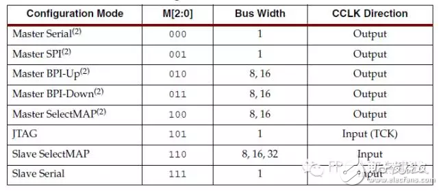
First, M[2:0] should be connected to 110 in the hardware, that is, Slave SelectMAP mode. In this mode, the bus width is divided into 8, 16, and 32 bits. This document is configured and read back in 32-bit mode. 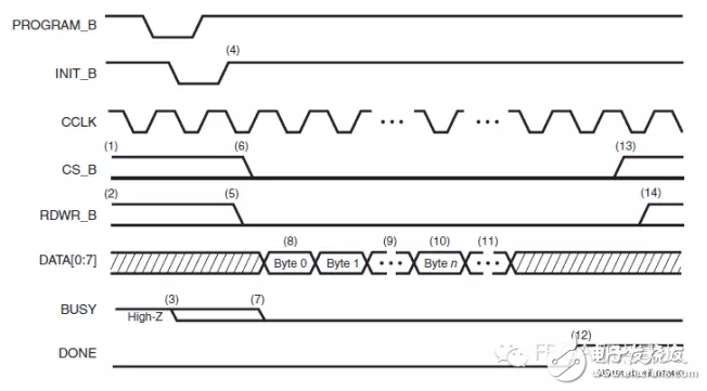
FFFFFFFF Dummy Word
000000BB BusWidthWord
11220044 8/16/32BusWidth
FFFFFFFF Dummy Word
FFFFFFFF Dummy Word
AA995566 Sync Word 
20000000 Type 1NOOP
30020001 Type 1 write1 words to WBSTAR
00000000 Warm BootStart Address
30008001 Type 1 write1 words to CMD
00000000 NULL
20000000 Type 1NOOP
30008001 Type 1 write1 words to CMD
00000007 RCRC
20000000 Type 1NOOP
20000000 Type 1NOOP
30022001 Type 1 write1 words to TIMER
00000000 TIMERvalue
30026001
00000000
30012001 Type 1 write1 words to COR0
02003F35 done@4 m@0l@0 gts@3 gwe@5
3001C001 Type 1 write1 words to COR1
00000000 COR1value
30018001 Type 1 write1 words to ID
03300093 ID code
30008001 Type 1 write1 words to CMD
00000009 SWITCH
20000000 Type 1NOOP
3000C001 Type 1 write1 words to MASK
00400000 MASKvalue
3000A001 Type 1 write1 words to CTL0
00400000 CTL0value
3000C001 Type 1 write1 words to MASKR
00000000 MASKvalue
30030001 Type 1 write1 words to CTL1
00000000 CTL1value
20000000 Type 1NOOP
20000000 Type 1NOOP
20000000 Type 1NOOP
20000000 Type 1NOOP
20000000 Type 1NOOP
20000000 Type 1NOOP
20000000 Type 1NOOP
20000000 Type 1NOOP
30002001 Type 1 write1 words to FAR
00000000 FARvalue
30008001 Type 1 write1 words to CMD
00000001 WCFG
20000000 Type 1NOOP
30004000 Type 1 write0 words to FDRI
50177910 Type 2 write1538320 words to FDRI
The FPGA configuration bit stream contains two types of configuration word instructions. The first type is a read/write operation instruction, and the format is as follows. 

leakage breaker can protect against overload and short-circuit. It can be used to protect the line from being overloaded and short-circuited as wellas infrequent changeover of the line in normal situation. It complies with standard of IEC/EN61009-1 and GB16917.1.