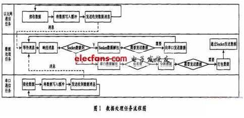
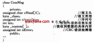
Train Dispatch and Command System ( TDCS ) is a modern information system that realizes transparent command, real-time adjustment and centralized control of trains at all levels of railway transportation dispatch. It is composed of the Ministry of Railways, Railway Bureau Central Area Network and station basic network. TDCS station extension is the equipment of the basic network of the station, which plays the role of information collection, upload and distribution, and occupies a very important position in the entire system. 1 Functional analysis In the station extension system, the station extension software mainly implements two functions: (1) Receive the dispatching commands of the dispatch center of the railway bureau and the train service terminal, after the command analysis processing, send them to the train for execution via the wireless dispatching command device; (2) Receive the status information sent by the computer interlocking device, wireless train number device, and wireless dispatch command device, and after parsing and repackaging, send the status information to the railway bureau dispatch center and vehicle service terminal. It can be seen from the above analysis that the system mainly has the following three functional modules: receiving status module, receiving command module and data processing module. Among them, the receiving status module is realized by RS 422 serial communication mode; the receiving command module is realized by Ethernet communication mode; the data processing module is mainly responsible for data processing and sending. 2 Creation of multi-task model Based on the Windows operating system, for the above three modules, this article established three tasks: serial communication task, Ethernet communication task, data processing task. The data processing task as the main thread, including data receiving and uploading, the processing process is as follows: (1) The receiving thread receives the data, puts it into the buffer, and uses PostMessage () to send a message to the main thread to notify the main thread that the data is stored in the buffer; (2) The main thread uses the ReadFile () function to read the buffer data; (3) The main thread judges whether the received data has changed: if there is a change, call the WriteFile () function or SendData () function to send a message, and clear the timer; otherwise, continue to wait. The specific flow of data processing tasks is shown in Figure 1. In this system, after using the AfxBeginThread () function to create Ethernet communication tasks, serial communication tasks, and data processing tasks, the message mechanism is used to communicate between multiple tasks, and the semaphore, mutual exclusion, etc. are used to implement threads. Synchronization of global variables and functions. 3 Communication protocol design and analysis A protocol is a rule that data senders and receivers must abide by. Part of this rule is the format of information that the sender and receiver recognize, that is, information structure. The other part is composed of the protocol type and protocol operator of the information structure. The conversation mode is transmission control. In this system, the types and lengths of the various data received from the serial port and Ethernet are inconsistent, and the data processing task must be clear about the type of data, the actual length, and the data itself in order to process them in different categories. Therefore, a data transmission protocol must be defined to ensure the reliability of communication and the availability of data reading. This article establishes corresponding data protocols for Ethernet communication and serial communication. 3.1 Ethernet communication protocol The information related to Ethernet communication includes computer interlocking device status information, wireless vehicle number information, and scheduling command information. This article defines a general data protocol encapsulation class for Ethernet information as follows: In this data structure, the message type is used to identify whether the message is interlocking device information, wireless vehicle number information or scheduling command information; the sequence number is used to judge the continuity of the received message; the CRC error detection suffix is ​​used to judge the reception The correctness of the message can be selected according to different generator polynomials; the received data array will be filled according to the corresponding content of the interlocking device information, wireless vehicle number information and scheduling command information. Embossed Membrane Switch,Flexible Membrane Switch,Rubber Membrane Switch,Control Membrane Panel Switch CIXI MEMBRANE SWITCH FACTORY , https://www.cnjunma.com
