Abstract: In order to overcome the shortcomings of traditional GPS positioning systems in indoor or building dense areas, and to better meet the needs of personal positioning, based on GPS0ne technology, a design and implementation scheme of portable personal positioning terminal is proposed. The terminal is composed of a positioning unit, a main control unit MCU, a UIM unit, an LED display and the like. The positioning unit uses the DTGS-800 GPSOne module of AnyData, and the main control unit selects the ultra-low power 16-bit single chip MSP430F147, with the aid of AT. The command and CDMA network implement functions such as personal position monitoring, positioning and alarm. The test results show that the positioning error of the terminal is less than 20 m, the indoor is less than 500 m, the initial positioning time is less than 20 s, and the alarm information can be transmitted to the CDMA network control center within 1 s. This article refers to the address: http:// At present, the personal positioning system integrating positioning, monitoring and alarm functions is mostly based on GPS/GSM (GPRS) technology. Although GPS (Global Positioning System) can provide high-precision, global coverage, there must be a direct path between the GPS receiver and the satellite, which makes the GPS positioning system in densely populated urban areas and buildings. There is a blind spot inside the object. 1 system hardware design 2 system software design The software design of the terminal has five modules: main program, button detection, battery detection, storage and serial communication. Figure 6 shows the main program flow. 3 System testing Through comprehensive testing in different environments, the results show that the system has the following functions: 1) Perform MPC third-party positioning (ie, network-side positioning); 2) Directly control the terminal for active positioning (ie, terminal-side positioning) 3) Support single positioning and continuous positioning; 4) Support MS-Based and MS-Assist positioning modes; 5) Can remotely set various parameters; 6) Have emergency alarm, cross-over alarm and over-speed alarm. 4 Conclusion Based on GPSOne module DTGS-800 and low-power single-chip MSP430F147, this paper designs and implements a personal positioning terminal integrating personal positioning, monitoring and alarming, which solves the problem that GPS cannot be located indoors, in tunnels, etc. The overall system power consumption is minimized due to the low power processor. It can work in the long-term standby, which brings great convenience to users and has high practical value. However, since the system uses the short message channel of the CDMA network to transmit information, the real-time performance is not ideal. In order to improve the real-time performance of the system, you can consider using the TCP/IP protocol built into the GPSOne module for information transmission. Fork Type Terminals,Insulated Bullet Sockets Terminals,Insulated Bullet Terminals,Type Fork Insulate Terminal Taixing Longyi Terminals Co.,Ltd. , https://www.longyicopperterminals.com
Keywords: Global Positioning System (GPS); GPSOne; personal location; location monitoring; CDMA
GPSOne integrates GPS, CDMAlX (Code Division Multiple Access Packet Data Exchange Network), GIS (Geographic Information System) and Internet technology. It is a positioning technology developed by Qualcomm for location-based services, using Client/Server. It combines wireless-assisted A-GPS and advanced forward-link AFLT triangulation technology for high-precision, high-availability and high-speed positioning. In an environment where A-GPS positioning technology cannot be used, it will automatically switch to AFLT triangulation technology to ensure the success rate and accuracy of positioning. Here, based on the GPSOne module DTGS-800 and the low-power single-chip MSP430, a personal positioning terminal with positioning, monitoring and alarm functions is designed and implemented. 
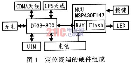
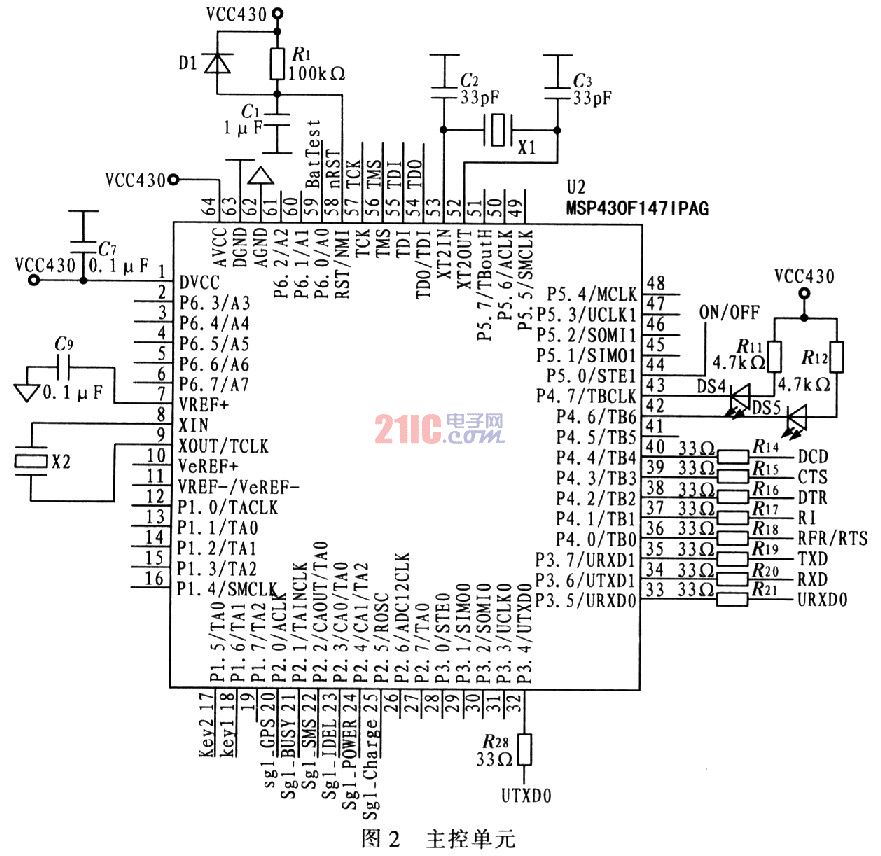
The hardware composition of the personal positioning terminal is shown in Figure 1. In order to solve the problem that GPS is difficult to locate in indoor and high-rise building dense areas, AnyData's DTGS-800 GPSOne module is selected. In order to reduce the size, reduce power consumption and cost, the main control unit MCU selects the ultra-low power 16-bit single-chip MSP430F147. The display uses LEDs. The MCU is responsible for controlling the GPSOne module to initiate a positioning request, receiving and parsing the information sent by the CDMA network control center, obtaining the current latitude, longitude and other information, and sending it to the control center or the operator's mobile phone by means of a short message. The main control unit MCU is shown in Figure 2. It includes the MSP430F147, an external high-speed crystal oscillator and a low-speed crystal oscillator. When high-speed processing is not required, the high-speed crystal oscillator can be turned off, and only a low-speed crystal oscillator can be used to reduce power consumption. The MSP430F147 has two serial asynchronous communication interfaces (USART), one of which (USART) The DCD, CTS, DTR, RI, RFR/RTS, TXD, and RXD pins are connected to the UAR-T1 of the DTGS-800, and the other (URXD0, UTXDO) interface is connected to the serial port of the PC for system debugging. The nRst, MS, TCK, TDI, and TD0 pins are connected to the JTAG socket for program download and online debugging; the keyl and key2 pins are respectively connected to "Help" and reserved buttons. The external LED DS3 and LED DS4 indicate the low battery and communication between the DTGS-800 and the MSP430, respectively; BatTest is used to detect the battery power. 
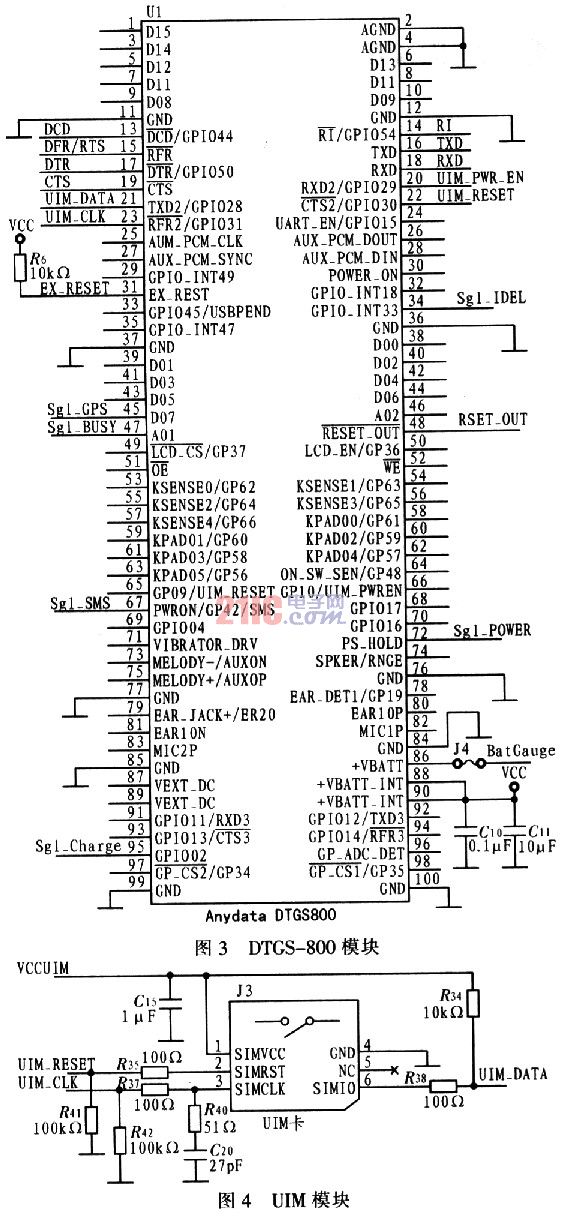
The DTGS-800 module is the main body of the positioning terminal. It integrates GPSOne device and uses GPSOne solution to locate. It supports the separation of RUIM from the machine card. It provides standard RS-232 data interface and standard AT command interface for data, voice and short message. And faxing provide fast, reliable, and secure transmission. The module can be powered by external power supply or battery. The battery supply voltage is +4.0 V±10%, and the external power supply voltage is +4.5 V±10%. The external power supply can also charge the battery through the power management device inside the module. . 
The circuit of the DTGS-800 module is shown in Figure 3. Among them, DCD, CTS, DTR, RI, RFR/RTS, TXD, RXD pins are connected to UART1 of MSP430F147, which is the communication channel between DTGS-800 and MSP430F147; UIM_DATA, UIM_CLK, UIM_PWR_EN, UIM_RESET are connected to UIM card (Fig. 4); Sgl_SMS, Sgl_IDEL, Sgl_GPS, Sgl_busy, Sgl_power, Sgl_ch-arge are system status indication signals, respectively connected to 6 LEDs for indicating new SMS signal, CDMA network signal, GPS signal, CDMA network busy, system power-on and battery charging status; The BatGauge is connected to the battery test end for detecting the battery temperature (Figure 5). 
The UIM card is a smart card for CDMA mobile phones, which functions like a SIM card in a GSM mobile phone. It supports dedicated authentication encryption algorithm and 0TA technology (0ver The Air), which can update and manage the data on the card through wireless air interface. The UIM card is fixed on the deck and connected to the outside through the 6 pins of the deck. As shown in Figure 4, UIM_RESET and UIM_CLK are pulled down by a 100 kΩ resistor, and UIM_DATA is pulled up by a 10 kΩ resistor.
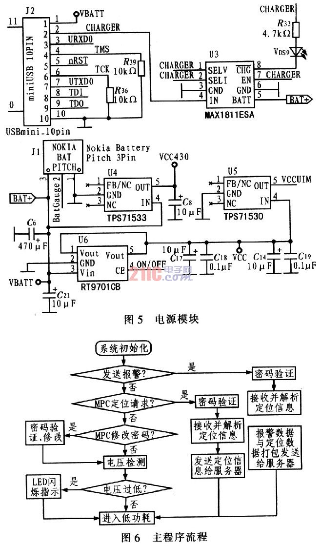
The power Battery and Charger modules are shown in Figure 5. The 88th and 90th pins of the DTGS-800 module are dedicated to battery-powered power input pins. If the module can be powered by external power or battery, connect the external power supply to pins 87 and 89 and the battery to the 88th and 90th pins. At this time, the external power supply can also charge the battery through the module's internal power management device. In the case that the module is only powered by the battery, a power on signal needs to be given to the module; when the second trigger is applied to the pin, the module is powered off.
The main program module is responsible for the initialization and data processing and storage of the other 4 modules. The module judges the correctness of the received data, extracts the location and other useful information, realizes the separation of the data and the temporary storage of the valid data in the on-chip RAM, and sends the useful information to the DTGS8-800 through the serial port, and then the DTGS-800 The form is passed to a third party. When the system starts, it is initialized first, including the watchdog, timer, voltage detection module (including MD converter), UART, button detection module and DTGS-800 initialization; after system initialization is completed, if there is no interrupt request, enter low Power mode to save power.
Both the button detection module and the battery detection module are executed in an interrupted manner. When a button is pressed, an interrupt is generated, the controller is notified to scan, it is determined which key is pressed, and then the corresponding processing is performed; the battery detecting module detects the battery power at a certain time interval, and notifies the controller if the battery power is insufficient. Start counting. If the voltage is too low for more than a certain number of times, the corresponding LED will flash to remind the user to charge.
If the user sends an alarm message, that is, press the Help button, an interrupt request is generated, the interrupt service subroutine is executed, the system exits the low power mode, enters the "HELP" state, initiates a positioning request, receives and parses the positioning information, and uses useful information and After the alarm information is packaged, it is sent to the server specified by HelpNum in the form of a short message. After the transmission is successful, the system enters the low power mode.
If the third party initiates the location request, the system exits the low power mode, enters the "MPC positioning" state, initiates the location request, receives and parses the location information, and sends the useful information to the designated mobile phone or server in the form of a short message. Returns to low power mode. The service password and MPC address can be set remotely via SMS in a specific format.
The initial positioning time of the system is within 20 S, the indoor positioning error is within 500 m, and the outdoor positioning error is within 20 m. The alarm information can be transmitted to the control center within 1 s. The alarm sensitivity is high, such as out of bounds, overspeed, and low battery. The system can work continuously for 24 hours, standby for 72 hours, and the operation is stable and reliable, which can meet the basic functional requirements of the personal positioning system.