1 I2C bus I2C is a two-wire serial bus developed by Philips. Now it has become an international standard. It has the advantages of improved protocol, more support chips, and less possession of I/O lines. It consists of the SDA data serial signal line and the SCL clock signal line, one for transmitting the communication data and the other for controlling the data transmission clock. The I2C can operate at 100 kb/s with the maximum bus load. The number of devices the device can connect to is limited only by the maximum capacitance of 400 pF. The process of data communication on I2C is shown in Figure 1. SDA and SCL are bidirectional signal lines connected to a positive power supply through a pull-up resistor. When the bus is idle, both signal lines remain high. Start signal when the SCL line is high and the SDA line transitions from high to low; a stop signal when the SCL line is high and the SDA line transitions from low to high. . Between the start condition and stop condition is the process of communication transmission. The host initiates the transmission and is the device that generates the clock signal and terminates the transmission. The host can be used as a receiving device or as a sending device. The start of communication is initiated by the host and can initiate a communication start signal at any time. However, there can only be one host and one slave communication on the bus at any time. In a conflict, the host must rely on an arbitration mechanism to decide which host to take over the bus. The slave communicates with the host, is addressed by the host, and responds to the command of the host. 2 overall design and hardware structure Multiple microprocessors are connected to the I2C bus, and a high-performance controller is used as the master controller to receive the data sent from the measurement processor. These data have been processed by the acquisition processor and do not require the main controller to perform further processing, thereby reducing the processing burden of the main processor. And when the received data reaches a need to issue a control command, a control command and a task parameter are sent to the control processor, and the specific operation of the control is processed by the control processor. The author uses a 32-bit high-performance microcontroller S3C2410 manufactured by Samsung Corporation and several low-power microcontrollers MC68S08QG8 (hereinafter referred to as QG8) produced by Freescale, and realizes the use of sensor devices, E2PROM memory devices, and display modules. system. The overall design block diagram shown in Figure 2. The S3C2410 uses an ARM920T core clocked at 203 MHz and is suitable for low-cost and power-sensitive requirements. Internally, an I2C controller is integrated, which can be conveniently controlled through registers. The QG8 is a member of the Freescale HCS08 family. All its microcontrollers use the enhanced HCS08 core with an I2C module and can be configured via registers. The slave address can be programmed. The processor is characterized by high performance, low power consumption, and low price. The I2C module has some registers for configuring I2C communication, IICA is used to configure the slave address of the microcontroller, the IICF divider register is software programmable to one of the 64 serial clock frequencies, and the IICC is used to initialize and control the I2C module. Communication; IICS status register is used to display the transmission status during I2C communication, and IICD data register is used to store the data to be sent and received. The I2C interface communication is achieved by reading and writing the status of these registers. 3 software implementation process To use ARM's I2C adapter under Linux system, we must first implement I2C driver under Linux system, develop application program based on this, and then implement 12c master-slave response program on 8-bit machine, and finally complete the software part of the system. design. 3.1 I2C Interface Driver For this 32-bit high-performance processor, using I2C module under Linux to complete the I2C core, I2C bus driver and I2C device driver three parts of the driver, only these three parts can work together to form a more suitable application of I2C driver program. The I2C-core.c file under the Linux-driven I2C folder implements the I2C core framework, which is the core part of the 12C that the Linux kernel uses for maintenance and management. It maintains two static Lists and records them in the system. I2C driver structure and I2C adapter structure. The I2C core provides interface functions that allow an I2C adatper, I2C driver, and I2C client to register in the I2C core when they are initialized, and log out when exiting. At the same time also provides the I2C bus read and write access to the general interface, mainly used in the I2C device driver. The driver bus adds a corresponding method for reading and writing to each I2C bus in the system, but it does not perform any communication, and it needs to wait for the device driver to call its function. The bus driver of S3C2410 is mainly realized by _i2c_xfex() and its dependent functions. The access to the device on all buses should ultimately be completed by it. The I2C device driver is a device-side implementation of the I2C hardware architecture. The device driver is mainly for the driver of the 8-bit processor QG8 part. This part defines two data structures, one of which is struet i2c_driver i2c{ Members include device driver names, id numbers, adapter additions, and more. Another data structure is struct i2c_client qg8_client{ It contains the device name, id number, device address, and driver used. 3.2 slave realization process The slave mainly implements I2C communication through interrupt response. In the main program, the slave sensor samples the sensor, puts the sampling data into the buffer and waits for the host to receive, or receives the control command sent by the host through the interrupt service routine. . Slave interrupt service flow chart shown in Figure 3. Slave interrupt service is roughly as follows: 1 During the processing of the slave interrupt service routine, the IICS_IAAS bit is used to identify the address match from the master. If the address information sent by the master matches the slave address set in the local initialization, IICS_IAAS is automatically set. In this case, the address match interrupt processing is performed. By judging this bit, it is confirmed whether the machine is the slave address called on the bus. If yes, it will send a response to the host to receive the data transmission of the address. Set the sending mode according to the read/write bit sent by the host, clear the address match flag, and take out the address sent by the host. According to the operation required by the host, corresponding processing is performed. The code is as follows: 2 If not, the address match interrupt, that is, the IICS_IAAS flag is not set, the data transmission interrupt processing, it should be judged whether IICC_TX is sent or received. Recognized as receive mode, the received data is stored in RAM, the pointer to the next unit, waiting to receive the next data. To identify the sending mode, it is first necessary to determine whether it is to end the sending or to switch to the receiving mode. Otherwise, send the next data to be sent to the IICD and wait for the host to receive. 3.3 host implementation process In most cases, the 8-bit machine is used as a slave to accept the host's control, but there are also host applications, as the host programming is as follows: First of all, the I2C module is initialized. The initialization process mainly includes the enable I2C module, the I2C module interrupt, and the response frame. In addition, the baud rate must be set. The baud rate is mainly set by the multiplication factor, the SCL frequency division number, and the bus speed. The baud rate needs to be set to balance the transmission rate and the length of time the data is kept on the line. Second, when establishing a communication connection from the slave address, it is necessary to normalize the slave address to be sent so that the last bit read/write bit indicates whether the master should send data to the slave or read data from the slave. Finally, the host enters the interrupt handling process after receiving the response. The host interrupt service first clears the interrupt by setting the interrupt flag IICIF, and determines the type of interrupt by reading the status register. There are three types of interrupts in the I2C of the QG8. One is to pass a byte, and the other is to match the received call address and arbitration. Lost. Loss of arbitration clears the arbitration lost flag and waits for the bus. After receiving an address response message, it sends or receives data according to the read and write requests. If the data is transmitted, the host sends an end signal. 4 Experiments and Applications Under the hardware environment set up (as shown in Figure 4), through the test programs written on each processor, the program finally achieved the desired goal. Each slave sampled the temperature value from the temperature sensor and could be processed in time. Send to the host through the I2C bus; when the host needs to control the absence of equipment, it only needs to send control commands and control parameters to the control slaves through the I2C bus, and control the slaves to respond in time according to the commands. The use of such a multi-processor monitoring and control scheme on high-frequency heating equipment will yield better results. During the process of heating the castings, the system is used to collect temperature at multiple positions of the castings. Each temperature measuring processor processes the data of each point in parallel, and the data of each point can be timely responded to by respective processors, making the system's Real-time control is greatly improved, eliminating the drawbacks of a single processor. However, since I2C has a certain limit on the transmission distance, it is not appropriate to use this solution in measurement and control equipment with a large distance between measurement points. 5 Concluding remarks Aiming at the contradiction between multi-point acquisition and processor processing capacity and limited interface appearing in the process of industrial control, a multi-processor measurement and control system established through I2C interface is proposed. The main task is to build hardware under the conditions of laboratory environment. Experimental platform, and on this basis, write a temperature control program. After testing, good data collection results were obtained, and the real-time performance of high-frequency heaters was greatly improved. In the industrial control, this scheme has more important significance to the handling of such problems. 64V Battery Pack ,Lithium Battery Box,Lithium Power Pack,Jackery Battery Pack Zhejiang Casnovo Materials Co., Ltd. , https://www.casnovonewenergy.com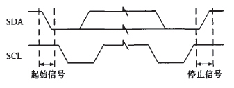
Figure 1 I2C communication 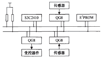
Figure 2 Overall Design
Name:"I2C QG8 Driver",
Id:I2C_DRIVERID_QG8,
Flags:I2C_DF DUMMY,
Attach_adapter:i2c_qg8_attach_adapter
Detach_client:i2c_qg8_detach_client,
Command:i2c_qg8_command,
}
Name:"12C QG8",
Id:1,
Addr:QG8_I2CADDRESS,
Adapter:NULL,
Driver:&i2c_i2c_driver,
slvRecvNotify:i2c_qg8_slvRcv,
} 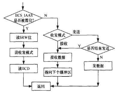
Figure 3 Slave interrupt service process
If(IICS_IAAS)
Do{HCC_TX=IICS_SRW,set tx=T,and clear IAAS,dummy=IICD;}
If(11CS_RXAK==1)IIcc_TX=0;
Dummy=IICD;IICD=IIC_DATA[i];i++;
IICC_IICEN=1;IICF=0x4B;
IICC_IlCIE=1;
IICC_TXAK=0;
IICC_TX=1;
IICC_MST=1;
IICD=slaveAddress; 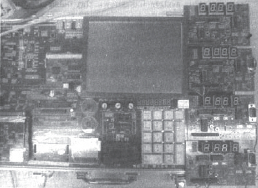
Figure 4 system hardware platform
Research on Multiprocessor Measurement and Control System Based on I2C Bus
With the development of computer and electronic circuit technology, embedded applications have penetrated into various fields of industrial control. However, in the industrial application, the processing equipment has realized intelligence and automation. At the same time, the complexity of the measurement and control equipment has become higher and higher, and the measurement data parameters required for processing the product have also increased. Due to the increasing demand for real-time access to the system, if a single measurement point is used, the data collection range is limited and the processing of the entire processing device will not be controlled very accurately. If a lot of point measurements are used to process the device, due to the limited processing capacity of a single processor, a large amount of data cannot be processed in time, and the processor interface is limited, which greatly limits the number of sampling points. Based on the principle of parallel processing, timely response, and simple implementation, this paper proposes a scheme for multi-processors to collect and control large amounts of data through the I2C bus.