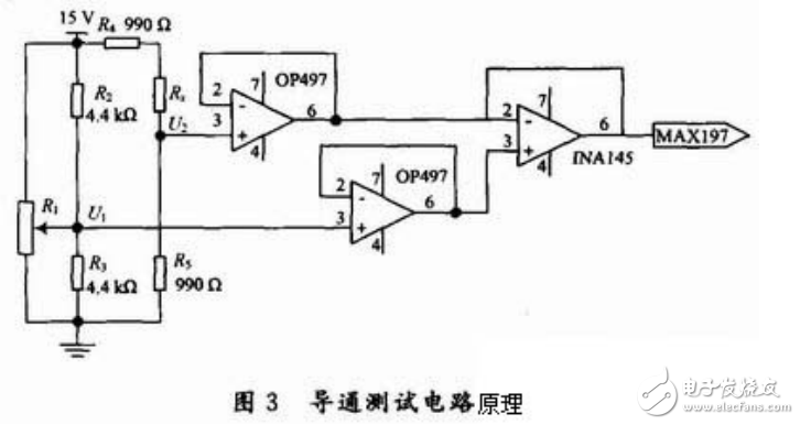
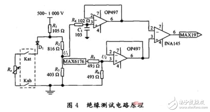
The intelligent cable test system is realized by a combination of a single-chip computer and an industrial computer, and has been tested. The hardware circuit design principle and engineering application scheme based on single chip microcomputer are described in detail. The test cable test system with insulation relationship meets the design requirements and greatly improves the efficiency and accuracy of the continent test. With the continuous improvement of the automation of aviation equipment, it also greatly affects the normal operation of the equipment. As the number of multi-core cable cores increases, the interconnection relationship becomes more complicated, which requires more test points for cable test equipment. The traditional manual test method is time-consuming and laborious, and the accuracy is poor. This paper proposes a new scheme for fault detection of aviation multi-core cables. The need for mass production cannot be engineered and the system composition and testing principles are explained. Conduction test circuit Since the on-resistance is small, generally ohmic, it is susceptible to external interference. The two arms of the Wheatstone bridge react to small changes in the power supply at the same time, and the output signal is sent to the differential amplifier, thereby eliminating the common mode. Interference can improve the accuracy of the test. The principle is shown in Figure 3. In Figure 3: R1, R2 and R3 form the reference circuit; R4, R5 and Rx are connected in series to form the main test loop. When the resistance to be tested Rx is zero, adjust R1 to make the bridge in equilibrium, that is, U1=U2, the circuit output is about zero, and the reference comparison voltage U1 is generated. Under the normal working condition of the circuit, after Rx enters the circuit in series, the balance of the bridge is broken, U2 becomes smaller, U1 and U2 are separated by the op amp OP497 and sent to the differential amplifier INA145 for amplification, and the amplified voltage signal is sent to 12 The bit precision MAX197 is sampled. Insulation test circuit For the insulation test circuit, since the input test voltage is 500 to 1 000 V, it is less sensitive to interference, so the insulation test circuit is implemented by a relatively simple resistor divider method. In Figure 4: Rx is the insulation resistance between the two wires tested; Kat, Kab are the input control relay and output control relay of Rx, respectively, which are gated by the decoding circuit, diode D1 protects the power supply; R1, R2 and R3 The voltage divider test circuit, R4 is the current limiting resistor, C1 is used to filter out the interference of the clutter, the voltage divider value of the test loop is input to the amplifier circuit after the op amp; MAX6176 is the high precision low noise reference power supply, after the voltage divider circuit and the follower After that, the reference comparison voltage is supplied to the amplifying circuit INA145, and the INA145 sends the amplified signal to the MAX197 for sampling. Global Electronic Measurement Technology and Market Leader - Keysight (formerly Agilent Electronic Measurement Division) 0.05mmT Grid for VFD Part,Electronics Controlling Grid,Bright Fluorescence Grid SHAOXING HUALI ELECTRONICS CO., LTD. , https://www.cnsxhuali.com
