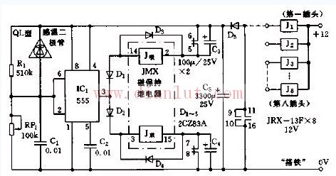
As shown in the figure, the shaft temperature alarm circuit. The alarm is composed of a sensing element, a time base circuit IC1 (555), a relay, and the like. The sensing element in this circuit uses a temperature sensing diode (QL type). It is usually placed in the axle box. Connect to the board via a self-closing plug. The temperature sensing diode QL is connected in parallel with the resistor R1. When the shaft temperature is normal, the resistor R1 and the potentiometer W1 are divided, so that the potential of the 6 pin of the 555 is lower than 1/3 VDD (= 4 V), and the 3 pin outputs a high level. The corresponding pulse relay (magnetic hold relay) JMX is in the released state. When the shaft temperature is higher than the preset temperature, the resistance of the diode QL becomes smaller, so that the potential of the 6-pin is higher than 2/3 VDD (=8V), the 5553 pin is changed to the low level, and the relay pull-in coil (J suction) There is a charging current flowing through and the suction contact moves. Subsequently, the contacts 5, 6 are disconnected, 7, 8 are closed, the contacts 9, 10, 11, 16 are closed, and the alarm relay J1 is sucked, which drives various alarms to emit sound and light alarm signals. When the shaft temperature returns to normal, the 5553 pin changes to a high level again, and the relay release coil (J discharge) has a current flowing again, causing the circuit to return to the original state: JMX is released. Wuxi Doton Power , https://www.dotonpower.com
The alarm temperature of the circuit can be set by adjusting the potentiometer W according to the season and the predicted temperature. In addition to the shaft temperature alarm, this circuit can also be used in other occasions where temperature control is required.