The RCA interface (CVBS)
Composite Video Broadcast Signal
CVBS is short for Composite Video Broadcast Signal. This is the most common video interface, the first application in the field of radio and television, then a lot of camera output support the CVBS interface, CVBS signals are interlaced video signal, and a resolution of 720 x576 (PAL) or 720 x480 (NTSC), CVBS is the analog video signal interface, has gradually been digital video signal interface and replace the hd video signal interface.
The AV interface (CVBS)
AV video interface English full name is: "Composite video connector", AV terminal is usually consists of three lines, transmission of video is usually yellow RCA terminal, the other with two red and white RCA terminal transmit audio, transmitted in AV terminal is analog TV signal source of three elements: Y, U, V, as well as the benchmark of the pulse signal synchronization. Y represents the brightness of the image (luminance, also called brightness), and contains the sync pulse, as long as there is signal Y can see black and white television image (in fact, this is the method of color TV and early black and white TV compatible). The U and V signals are loaded with color data. The U and V are first mixed into two sets of orthogonal phases ina signal (the mixed signal is called Chrominance), and then summed with the Y signal. Since Y is the fundamental signal and UV is mixed with the carrier, this summing action is equivalent to frequency division multiplexing.
Video Record Board,Cvbs Memory Board,Video Controller For 4 Inch Lcd,Lcd Controller With Cvbs Input Tonya Display Limited , https://www.tydisplay.com
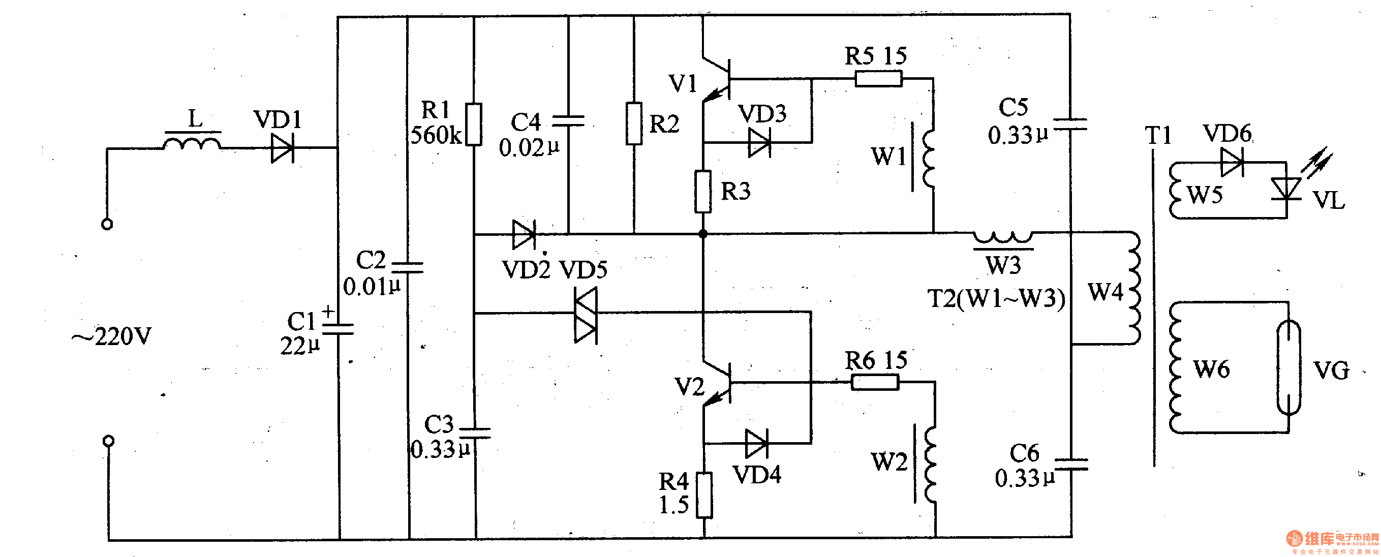
Circuit Operation The push-pull oscillation circuit consists of transistors Vl, V2 and oscillating transformer T2 (Wl-W3), pulse transformer T1, current limiting resistor Rl, charging capacitor C3, double-question trigger diode VD5 and so on.
The half-wave rectification and filtering circuit is composed of a filter inductor coil L, a rectifier diode VD1, and filter capacitors Cl, C2 and the like.
After the power is turned on, the AC 220V voltage is rectified by L filter and VDl, and a voltage of about +280V is generated at both ends of the Cl to supply a push-pull oscillation circuit.
At the instant of power-on, Vl is turned on, and the bidirectional trigger diode VD5 is turned off due to the charging effect of C3. When the charging voltage across C3 rises to 32V, VD5 is triggered to turn on, turning V2 on. During V2 turn-on, C3 gradually discharges, which in turn causes V2 to turn off. After Vl is turned on, under the action of the pulse transformer Tl, a positive feedback voltage is generated on W1 and W2, and the voltage is applied to the bases of V1 and V2, respectively, so that Vl and V2 are alternately turned on and off (ie, when Vl is turned on, V2 is turned off; when V2 is turned on, Vl is turned off), and the push-pull oscillation circuit oscillates.
After the push-pull oscillation circuit operates, a high-voltage pulse is generated on the secondary winding W6 of the pulse transformer T1 to operate the ozone generating sheet VG to generate ozone. At the same time, the light-emitting diode VL also lights up.
Component selection
Rl-R6 uses 1/8W metal film resistors.
VDl-VD4 and VD6 select 1N4007 type rectifier diode; VD5 selects DB3 type bidirectional trigger diode.
Vl and V2 select high-pressure silicon NPN transistors of the 2SC2653 or BU406.
A magnetic core inductor of L of 5 mH can be wound around the skeleton by 210 åŒ with an φO.25 mm enameled wire.
The pulse transformer Tl can be modified by using 14in (inch) black and white TV output transformer. When the system is modified, the high voltage package is used as W6. On the low voltage package, φ0.45mm enameled wire is used to wrap 168åŒ as W4, and φ0.23mm enameled wire is used.åŒ as W5 (wound at the outermost layer); W1-W3 of T2 is wound on the same magnetic ring with φ0.2mm single-core plastic copper wire, where Wl and W2 are respectively wound around 3åŒ, W3 is wound around 9åŒ.
Ozone generating sheet VG is selected from Z-10 or Z-15, Z-20 and other models.