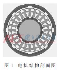
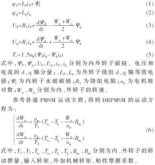
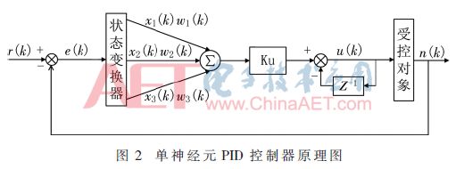
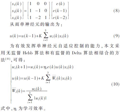
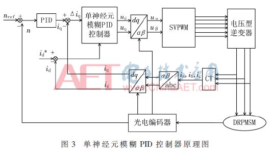
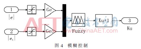
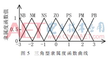
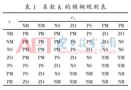
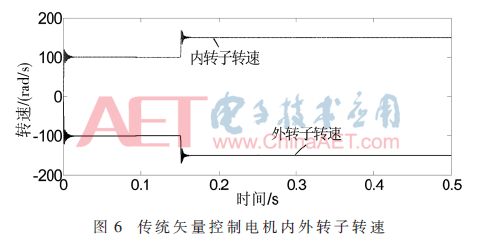
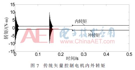
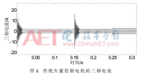
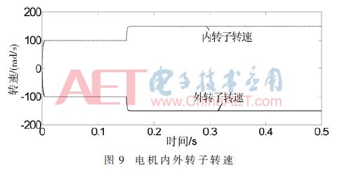
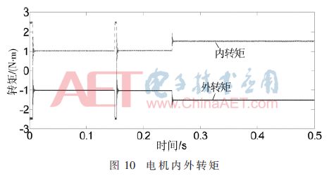
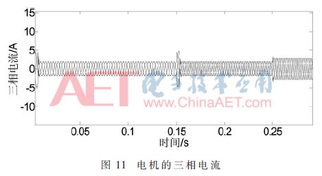
Abstract: Aiming at the shortcomings of traditional PID control methods such as parametric perturbation and poor anti-interference ability when controlling dual-rotor permanent magnet synchronous motor, a single neuron fuzzy PID control method is proposed. Firstly, the mathematical model of the dual-rotor permanent magnet synchronous motor is established and a single neuron fuzzy PID controller is designed. Then the system design and simulation are realized by MATLAB. Finally, the simulation results of traditional PID and single neuron fuzzy PID control are compared and analyzed. The simulation results show that the single neuron fuzzy PID control can significantly improve the robustness of the system and make the dual-rotor permanent magnet synchronous motor control system have better Dynamic and static performance and anti-jamming capability. 0 Preface During the process of underwater vehicle travel, two conventional motors or a single conventional motor plus a complicated planetary reducer drive system is used to drag the double propeller to rotate, in order to maintain its stable attitude. The former has a high cost of the transmission system, the latter has a complex structure, is prone to failure and has a low mechanical transmission efficiency [1]. The permanent magnet motor is used in wind power generation, but the wind power generation is greatly influenced by the weather, and the wind speed must reach a specific range before the voltage can be used. If the wind speed is too small or too large, the resulting voltage cannot be integrated into the grid, thereby making permanent magnet motors The design of wind turbines produces a narrow range of available voltages [2]. The dual-rotor permanent magnet synchronous motor adopts inner and outer rotor and intermediate stator structure, which has high reliability, high utilization rate of stator core, and high system operation efficiency [3]. The motor profile is shown in Figure 1. The gyro effect can be countered by itself during navigation, and the counter-rotating propeller system can be driven directly. In the field of wind power, the available voltage range can be broadened. Due to the above advantages of DRPMSM, it has attracted more and more attention from experts and scholars. Dual-rotor permanent magnet synchronous motor is a typical nonlinear strong-coupling system. During the actual operation, it will affect the control accuracy and system stability due to interference or complicated changes. The fuzzy control is used to control the dual-rotor motor, but the fuzzy control is sensitive to the choice of fuzzy rules and the real-time performance cannot be guaranteed. The single neuron PID control method used in [7] can optimize the motor starting performance, but the controller gain cannot Self-adjustment is realized; the sliding mode variable structure is used in the literature [8] to control the permanent magnet synchronous motor, but the sliding mode track cannot be continuous when the reverse switching is performed, and the control process is complicated. Based on the above problems, a single neuron fuzzy PID control method is proposed in this paper. The system simulation model is established in MATLAB environment, and the simulation results of traditional PID control and single neuron fuzzy PID control are compared. 1 mathematical model of double rotor permanent magnet synchronous motor Dual-rotor permanent magnet synchronous motor is a new type of motor. Its difference from ordinary PMSM is that the original stationary stator can also rotate, so the two have the same electromagnetic relationship. Before the establishment of the motor mathematical model, the following ideal assumptions are made[9] ]: (1) The symmetry of the motor phase windings; (2) The motor has a sinusoidal back-EMF waveform; (3) ignore magnetic saturation; (4) Ignore hysteresis loss. With reference to an ordinary permanent magnet motor, a mathematical model [10] of a dual rotor motor can be obtained as follows: 2 controller principle and system design 2.1 Single neuron PID controller principle The single neuron controller is based on the structure and characteristics of human brain neurons. The model is shown in Figure 2. In Figure 2, r(k) is the given speed signal, n(k) is the actual feedback signal, u(k) is the output value of single neuron PID controller, w1(k), w2(k), w3(k) The weighting coefficients correspond to x1 (k), x2 (k), and x3 (k), respectively. Use the error between the given speed r(k) and the actual output signal n(k) as the control deviation: Then through the state converter into the state quantity x1, x2, x3 required for neuron learning control, so as to obtain: Using the above learning rules system can automatically adjust the weight of each input. Applying this control strategy to a dual-rotor permanent-magnet synchronous motor can improve the anti-jamming ability of the control system, simplify the complexity of the algorithm, and achieve smooth saturation of the speed controller. However, the K value of the neuron proportional coefficient is artificially set, and once it is selected, it cannot be dynamically adjusted and it is very difficult to select. If the K value is too high, the system will overshoot and the system response time will increase; The system response speed becomes slower and real-time performance is not guaranteed. 2.2 Single Neuron Fuzzy PID Controller Design Because of the difficulty in selecting the neuron proportional coefficient in single neuron PID control, this paper designs a single neuron fuzzy PID controller based on this, and its schematic diagram is shown in Figure 3. Based on the disadvantages of single neuron PID control, this paper adjusts the controller gain through a fuzzy control strategy. The control strategy is shown in Figure 4. The performance of fuzzy PID control system depends on the formulation of fuzzy control rules. On the basis of analyzing the vector control speed response curve, the fuzzy control rules are formulated [12]. In this paper, seven terms are used to describe the input and output variables, namely {NB, NM, NS, ZO, PS, PM, PB}. The triangular membership function curve is used as the membership function of the input/output variables, as shown in Figure 5. It calculates less work and has high sensitivity. Fuzzy reasoning uses the Mamdani method [13], and anti-fuzzification uses the weighted average method. Table 1 shows the control rules. 3 simulation results and analysis Based on MATLAB, two simulation control models for motor vector control and single neuron fuzzy PID control were built. The parameters of the motor were as follows: the motor pole pair number was 4, the rated voltage was 220 V, and the inner and outer armature resistance was 1.437 5 Ω. The permanent magnet flux is 0.175 Wb, the viscous friction coefficient is 0, and the equivalent inductance of the dq axis of the motor rotor is 4.25×10⁻³ mH. In the MATLAB/Simulink setup interface, the simulation model start time is 0 s, the stop time is 0.5 s, and the initial setpoint speed value is 100 rad/s; at 0.15 s, the internal and external rotor setpoint speed is from the initial 100 rad/s. The jump becomes 150 rad/s; at 0.25 s, the rotor torque of the inner and outer motors changes from 1 N·m to 1.5 N·m. Based on this simulation, the output characteristics and response speed of the motor are analyzed. The experimental results are compared with the traditional vector control method, so that the correctness of the mathematical model of the dual-rotor permanent magnet synchronous motor and the control effect of the corresponding control algorithm can be verified. Figures 6 to 8 show the response curves of the rotor speed, torque, and three-phase currents of the two-rotor permanent magnet synchronous motor in the internal and external rotors, respectively, under conventional vector control. From the waveform analysis of the simulation results, it can be seen that the speed response curve of the internal and external motors obtained by the traditional vector control method has a large overshoot and a long time oscillation adjustment process; for the motor torque, when the rotation speed changes The torque changes significantly; and for the three-phase current, when the motor reaches a predetermined speed and the speed is changed, the three-phase current changes greatly, and the motor can reach the set value in a long time. Fig. 9 to Fig. 11 are response curves obtained using the single neuron fuzzy PID control method. It can be seen that the motor speed reaches a set value of 100 rad/s in a short period of time. When the motor reaches a stable speed and continues for a period of time At 0.15 s, the internal and external rotor speeds were changed from 100 rad/s to 150 rad/s. As can be seen from Figure 9, compared with the vector control, when the set speed changes, the speed of the inner and outer rotors quickly reach a given speed, and the response speed is faster. Similarly, the torque response curves of the internal and external motors can be seen. In a short time, the internal and external rotor torque reaches a given value. From Fig. 10, the electromagnetic torque of the internal and external motors is kept at a given value of 1 N·m. The moment does not change. After some time. As the set speed is increased at 0.15 s, the internal and external rotor torque fluctuates. However, as can be seen from FIG. 10, the torque quickly returns to a stable value. When the three-phase current of the motor is given the internal and external rotor speed and torque, it reaches a stable value at a relatively high speed. After reaching a stable and steady state and continuing for a period of time, the three-phase current fluctuates due to changes in the speed. But then quickly stabilized, as shown in Figure 11. At 0.25 s, the torque is artificially changed to 1.5 N·m. From Fig. 10, it can be seen that the internal and external rotation speeds of the motor are little affected by the torque change, and there is almost no change. In Fig. 10, the torque response of the motor changes when the magnitude of the torque changes. It was very fast and it quickly reached 1.5 N·m. Figure 11 shows that when the three-phase current waveform changes while the torque is changing, it can respond quickly and achieve a more stable state. Overall, the simulation results show that the simulation results of the single-neuron fuzzy PID control system for dual-rotor permanent-magnet synchronous motor (DRPMSM) designed in this paper can maintain stable speed, torque, and three-phase current during operation. When the torque changes in a certain period of time, it can also stabilize in a short time. Compared with the traditional vector control method, the control system designed this time has faster response speed and better simulation results. 4 Conclusion This paper analyzes the working principle of double-rotor permanent magnet synchronous motor (DRPMSM), establishes the mathematical model of the motor, builds a single neuron fuzzy PID control system, and conducts a comparative simulation study. The simulation results show that the single neuron fuzzy PID control method can achieve the desired experimental response speed under the condition of changing the speed and torque, and has better dynamic and static performance than the traditional vector control system. Through the analysis of the simulation results, the characteristics of the speed, torque and phase current of the dual-rotor permanent magnet synchronous motor and the mutual influence between them are thoroughly understood. At the same time, the results of this experiment also provide reference for further analysis and design of the DRPMSM's body structure and control strategy. Of course, this article does not do correlation analysis on the mutual interference between the rotors inside and outside the motor. How to optimize the control strategy to optimize the performance of the controller remains to be further experimental analysis. In the future research, it is believed that the optimal design of the body structure, the motor The improvement of the mathematical model and the innovation of the control algorithm will be the focus of research on the dual rotor permanent magnet synchronous motor. Semiconductor Moly Semiconductor Moly YANGZHOU POSITIONING TECH CO., LTD. , https://www.cnchipmicro.com