Image 6 The layout of the grounding wire starts from the power transformer and is divided into left and right channels. It uses bare copper wire or silver-plated copper wire with a diameter of about 1mm and is welded to the pre-installed copper solder pieces respectively. The output terminal goes to the power amplifier stage, then to the inverting stage and the front input stage. And pay attention that the high-current grounding wire of the power transformer and the output end cannot directly form a loop with the low-current grounding wire of the input stage. Although all grounding wires in the machine are measured with a multimeter, they are 0Ω, but for AC signals, the potential difference is large and the wiring is improper. Will cause noise interference. The filament supply of the combined power amplifier is divided into 3 groups, the left channel and the right channel power amplifier tubes are connected to each group, and the front stage left and right channels are combined into one group. In order to prevent AC induction, the filament wiring should all use the hinge method. The roots are twisted together so that the alternating electromagnetic fields can cancel each other out. In order to reduce hum interference, the center tap of the filament must be grounded. For the power group without the center tap of the filament, one 100Ω-200Ω can be connected to the two ends of the filament, and the center tap of the resistance can be grounded to receive the same effect. 3. Shielded isolated wire The sensitivity of the input tube grid is very high, and it is easy to produce interference of AC clutter signals. Because the input tube grid and the input terminal of the input tube and the volume control potentiometer lead are long, it is necessary to use a metal shielded isolation wire, and the outer layer of the metal The ground end of the braided wire should be arranged at the cathode ground of the input tube. 4. Install high-voltage power supply The high-voltage power supply part of the tube power amplifier is simpler than the power supply circuit of the transistor power amplifier, and it is easy to debug without the need for voltage regulation and large-capacitance filtering. This is mainly because the tube power amplifier is a high-voltage small-current type, and the static current and full-load current of the power amplifier stage change little, generally It fluctuates between 0.2-0.5A, so the capacity of the filter capacitor can be satisfied by dozens of μF; and the transistor power amplifier is a low-voltage high-current type, and the current changes greatly when the zero signal and the full signal are generally 0. It varies from 5 to 5A, so the filter capacitor must use thousands to tens of thousands of μF. However, the tube power amplifier is more complicated to suppress hum. It must be considered in design and wiring, such as the routing of high-voltage power supply, the installation location of the power transformer, and the radiation of external electromagnetic fields. The high-voltage power supply part of this power amplifier is supplied by the left and right channels after bridge rectification. It adopts a CRC-type filter network. The total power supply is directly connected to the ground after the bridge rectification. The coupling capacitors are connected to the ground at the near end of the left and right channels respectively. Because the internal resistance of the high-voltage power supply is small and the efficiency is high, a small ripple factor can be obtained. The wiring of the high-voltage power supply should be supported by a wiring bracket to prevent interference with all levels in the machine. 5. Install all levels of components In order to prevent noise interference, the resistance of this machine should use metal film resistors. In addition to indicating power consumption, all 1W metal film color rings or Dahongpao resistors are used. Coupling capacitors have a great influence on the whole machine. Special audio capacitors, CBB polypropylene capacitors, CZM oily capacitors and other fast conversion rate capacitors can be used. When coupling a capacitor with polarity, its polarity cannot be reversed, the high potential is connected to the positive terminal of the capacitor, and the low potential is connected to the negative terminal, which is conducive to normal charging and discharging in the circuit. At the same time, the capacitor used must not have a slight leakage, and can be installed after the megohmmeter is detected. Because of the slight leakage of the capacitor, the resistance characteristic of the capacitor increases, the loss increases, and the amplifier causes phase shift and intermodulation distortion. The volume control potentiometer should also be checked before installation, there must be no jump and dead point, otherwise it will cause contact noise. Sealed WTH-1W-Z type or S type should be used, but X type linear potentiometer can not be used for volume control, because the volume controller must use exponential type, so as to meet the loudness characteristics of the human ear. The installation of resistance and capacitance components at all levels must be grounded at one point or nearby to prevent cross interference. In particular, the grounding of the gate resistance, cathode resistance and bypass capacitor at all levels is particularly important. There can be no more wires between them, otherwise it is easy to produce induced hum, because if you use wires, some resistance will inevitably form The potential difference means that an AC source is connected in series between the cathode and the grid. After step-by-step amplification, obvious hum interference will occur. The impedance of the grid of the electron tube is high, and the sensitivity is also very high. In order to prevent the interference of the electromagnetic field in space, it cannot cross and cling to the DC high-voltage wiring or components. For this reason, the cathode resistance and the grid resistance should be as close as possible to the bottom plate during installation The screen element is placed on the uppermost layer by scaffolding. Picture 7 The matching work of power amplifier tubes is not as strict as that of transistors, because the parameters of the same type of transistors have large differences in amplification factors and other parameters, and the amplification factors of the tubes are not different. As long as the same batch of products of the same model and the same manufacturer are used, the performance parameters are basically The same, the pairing work can be omitted. 1. DC voltage measurement at all levels When the output AC voltage of the high-voltage winding of the power transformer is 300V, after the bridge rectifier circuit composed of diodes, the DC high voltage of the first stage should be 420V. After filtering and smoothing the network composed of CRC, a DC high voltage of about 400V will be obtained. Separately for left and right channel amplifiers. If the EL34, 6L6 and other tubes are used for the push-pull amplifier tube, the screen voltage should be between 360-400V. The resistance value of the cathode resistance of the power amplifier tube depends on the type of power amplifier. For example, when the cathode resistance is 25011, when the total current of the power amplifier stage is 100mA, the voltage of the cathode of the power amplifier tube to ground should be 24-26V. The DC voltage of the screen of the pusher tube 6N6 is 280-320V. If it is used for class A amplification, the cathode resistance will be 14-16V when the cathode resistance is 20-24kΩ; if it is used for class AB amplification, the cathode resistance It can be 30-47kΩ, so that the output voltage of the AC signal can be increased, and the DC voltage of the cathode to ground can reach 25-30V. Inverter tube 6N11 has a screen voltage of 240-260V and a cathode-to-ground voltage of 85-90V. The gate potential of the tube should be about 2V lower than the cathode potential. If it is difficult to purchase 6N6, 6N11 double triode in the purchase of electron tubes, ordinary double triodes such as 6Nl, 6N2 can also be used instead. If using 6N8P, 6N9P and other dual transistors, the base should be replaced by a small nine-pin lamp holder and a porcelain eight-pin lamp holder. When using ordinary bipolar transistor instead, it must be noted that the cathode potential of the input tube and inverter tube cannot be too high, because the voltage limit voltage between the ordinary bipolar tube cathode and the filament is only 100V, so the cathode The potential must be controlled below 80V. The working state of the Class A power amplifier tube must be maintained at the straight part of the center of the grid pressure screen flow characteristic curve. Therefore, the grid negative pressure of the Class A power amplifier tube should be carefully adjusted to ensure that the average screen current value is constant. The average screen current should be controlled at 100, 120mA. The specific calibration method is to use a 500mA DC ammeter, which is connected in series in the screen loop of the power amplifier tube. When the audio signal is input to the gate of the power amplifier tube, if the screen current increases, it means that the gate of the power amplifier tube is negative. The voltage is too low; conversely, if there is an audio signal input, the screen current of the power amplifier tube decreases accordingly, indicating that the grid negative pressure is too high. Therefore, the screen flow change of the class A amplifier must be maintained at about 10%. If the screen flow change is large, it indicates that the working state is unstable or has entered the working state of class AB. Picture 8 3. Class AB power amplifier grid negative pressure adjustment The gate negative voltage adjustment of the class AB amplifier stage must be performed after the audio signal is injected. The negative voltage of the grid of the power amplifier tube is for the cathode. Therefore, when measuring, the multimeter should be placed on the DC voltage 50V, the negative meter rod should be connected to the grid of the power amplifier tube, and the positive meter rod should be connected to the power amplifier tube. cathode. The screen current of the class AB amplifier stage varies greatly. Generally, the screen current changes more than 1 times from the zero signal to the full load signal. Therefore, when adjusting, the zero signal is the zero signal when the volume controller is placed at the minimum position; At the maximum position, it is a full signal, the characteristics of various power amplifier tubes are different, and the change amplitude of the screen current is also different from the negative value of the grid. When EL34 and 6CA7 are used as the power amplifier tube, the negative voltage of the grid is -26V, and the change of the screen current from the zero signal to the full signal is 90-180mA; if the power amplifier tube is 6L6, 6P3P, the negative voltage of the grid is- 22V, the change value of the screen current is 88-130mA; if KT88 and 6550 are used as the power amplifier tube, the negative voltage of the grid of the tube is relatively deep, which is -46V, so the driving voltage of the previous stage must be increased accordingly. The amplitude of the screen current when the power amplifier level changes from zero signal to full signal is large, generally 120-260mA. Picture 9 The negative feedback of the whole machine from the power amplifier level to the input level of this circuit is very low, only controlled between 6-10dB. In this way, the stability of the whole machine can be maintained without affecting the transient response characteristics of the whole machine. If the negative feedback resistor is connected, the output of the whole machine is enhanced, which means that the phase of the output terminal is reversed, and the phase can be changed at this time. When the negative feedback resistor is connected, the noise of the whole machine should be reduced, the frequency response should be broadened, and the stability of the whole machine should be improved. After turning on the power switch, there was no sound. After checking, it was found that the fuse inside the machine had blown. Picture 10 Figure 10 (b) shows a bead shape after fusing. It shows that there is an instantaneous large current overload in the machine, such as a strong signal injection that causes a large current to be instantaneously generated or a self-excited oscillation in the machine itself. Figure 10 (d) The pipe wall is black or burst. The internal short circuit of the power transformer, the breakdown of the power rectifier diode, and the short circuit of the high-voltage circuit to ground cause a large surge current. After the serious faults in the machine are eliminated, check for silent faults. Before starting, check whether the connection between the speaker and the output transformer is good. If the output transformer cannot send the signal to the speaker, the output transformer itself will make a slight sound for a long time. It will cause the primary side package of the output transformer to burn out. After all voltages and currents are checked, the audio signal can be injected for testing. First place the volume control potentiometer in the middle position, check whether the input terminal socket and the socket are in good contact, whether the metal shielding wire from the input terminal to the input tube grid is short-circuited or open, whether the input tube and the socket are in good contact, check everything After no error, if the injected signal is still silent, it must be checked from the next level. Connect the outer layer of the output terminal of the audio signal source to the ground terminal of the power amplifier. The signal output terminal sends the audio signal to the inverter tube and pushes the grid of the tube one by one through the DC blocking capacitor. If there is sound in the speaker, it indicates a failure Out of the previous level of this level, you should carefully check whether the components in the circuit are damaged, or there is a wrong pin connection in the circuit. 2. Severe hum fault The hum of the tube power amplifier is more significant than that of the transistor power amplifier. For a self-made tube power amplifier, a slight hum in the speaker is normal, but if the hum is very obvious, it means that there is a fault in the power amplifier. The power part has the highest probability of causing hum. Insufficient capacity of the filter capacitor or leakage current will cause hum. When the first-stage filter capacitor is severely leaked, not only the exchange sound is loud but the DC high voltage output is low; when the second-stage filter capacitor is severely leaked, not only the exchange sound is loud, but also accompanied by howling. Poor welding or poor grounding of the electrostatic shielding isolation layer in the power transformer will also cause modulation hum, but if the power transformer cannot be disassembled and re-wound, the remedy is to bridge one between the AC power inlet and the bottom plate The disadvantage of capacitors above 0.01μF / 400V is that there will be a slight numbness phenomenon on the case. In addition, when the power transformer is installed, if the iron sheet is directly attached to the bottom plate, the eddy current magnetic field generated by the iron core will extend to the bottom plate, thereby inducing hum. In this way, an insulating gasket can be added between the power transformer and the bottom plate to reduce or eliminate hum. Input pre-stage is also easy to induce AC noise. Turn off the volume potentiometer first. If the audible sound is reduced, the volume is increased, and the audible sound is also increased, it indicates that the fault occurs at the input stage. Induced hum, can be connected in parallel with 100kf ~ small resistance at both ends of the input terminal socket. In addition, the volume of the potentiometer shell is poorly grounded and there is induced hum between the shielding layers. In addition, there is an improper layout of the ground loop of the input stage. Leakage between the cathode of the input tube and the filament will produce AC noise. The poor grounding point of the gate resistance of the inverting stage and the driving stage or the large resistance value can also cause AC noise. The position of the coupling capacitor device between stages is improper and is induced by the nearby electromagnetic field. The layout and the location of the ground point should be carefully checked. After the pre-stage fault is eliminated, all the pre-stage electron tubes can be unplugged, leaving only the power amplifier tube, whether there is hum. When the power amplifier tube is old and aging, or the power amplifier tube filament voltage is insufficient, it will cause AC noise, you can replace the other power amplifier tube test. When the gate resistance or cathode resistance of the driving stage is too high, it may cause blocking distortion. You can appropriately reduce the resistance of its resistance to eliminate its blocking distortion. When the characteristics of the two tubes of the push-pull power amplifier tube are greatly different, or the working state of the two tubes is completely out of balance, the louder the volume is, the more serious the distortion will be. The power amplifier tube should be readjusted or replaced to balance the push-pull amplifier. When the impedance of the power amplifier tube and the output transformer are severely mismatched, the phenomenon of larger volume and more obvious distortion will also occur. 4. Noise failure When the amplifier is playing normally, it is accompanied by irregular clicks or squeaks as a noise. First, the interference noise caused by the AC power supply should be eliminated, as well as the factory noise caused by various household appliances. You can unplug all the pre-amplifier tube and push-amplifier tube first, and focus on checking the power amplifier level and power supply level. If the insulation performance of the high-voltage winding inside the power transformer is poor, internal flashovers often occur and the ears can be listened to, which helps to determine the fault. The output transformer of the power amplifier level often has internal sparks due to poor insulation between layers. In addition, the power amplifier tube itself is of poor quality, and there will also be inter-polar flashovers, which will cause noise. After the rear-stage fault is eliminated, all the front-stage electron tubes can be plugged in, focusing on checking the front-stage grid resistance and screen load resistance. For example, when a low-quality carbon resistor is used for assembly, the quality of the resistance itself is unstable. It often causes poor internal contact, which leads to the phenomenon of occasional disconnection in the circuit. The internal contact of various input terminals of the front stage is poor, and the internal contact of the volume potentiometer will produce noise.
When people search gaming laptop, indicates that they need high performance 15 Inch Gaming Laptop, comes with big screen size, high cpu, large memory and storage, high resolution display, quality bigger 12000mAh battery, 2MP Camera, etc. 15 or 14 inch 500 Dollar Gaming Laptop, 10th generation laptop, 11th gen gaming laptop, 12th generation laptop, Laptop Intel Core I7, Intel I5 Laptop are the Top 10 Gaming Laptops. Every gamer want to buy Gaming Laptop with higher processors, big 8GB, 12GB, 16GB system memory ram, large Solid State Drive so that can handle or storage digital data at a high speed, 1920*1080 Full HD Slimmer screen provides user stunning vivid visuals, fingerprint reader, backlight keyboard, etc.
Nowadays 11th Laptop is the most competitive cpu, cause performance is better than 10th, but price is nearly same; besides, Solid State Drive cost 512GB is the most welcome and competitive one.
Of course, You can also contact us directly and share your exact requirements, so that we can send the right and valuable information quickly.
Gaming Laptop,Top 10 Gaming Laptops,500 Dollar Gaming Laptop,15 Inch Gaming Laptop,Buy Gaming Laptop Henan Shuyi Electronics Co., Ltd. , https://www.shuyicustomtablet.com
Install all kinds of small parts such as switches, potentiometers, wiring brackets, input and output terminals, and tube lamp holders one by one on the general base plate. The ceramic lamp holder must pay attention to the orientation of the illustration when installing, so as to keep the wiring distance closest . Among them, the power transformer and the left and right channel output transformers are bulky and cumbersome, so they should be installed after all small parts are welded, because the bottom plate must be turned on all sides during the installation process, which is easy to damage the appearance. 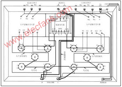
Figure 6 Wiring diagram of tube combined power amplifier
1. Ground wire
2. Cloth filament
The traces or components of the screen and grid of the electron tubes at all levels should be as far away as possible, and cannot be tight. In order to make it easy to distinguish, the high voltage line is generally red, the tube screen is orange and yellow, the grid is blue and green, and the cathode is brown and black. 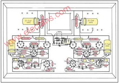
Figure 7 Assembly drawing of the combined power amplifier components of the electron tube
Commissioning of the combined amplifier
After all the parts are installed and welded, install the power transformer, the left and right channel output transformers, and carefully compare all the components with the circuit diagram. Check whether there are leakage soldering or wrong connection, and debug can only be done after everything is correct. .
Before commissioning, the output terminal should be connected to a dummy load, which can be replaced by a resistor within 100Ω and above 10W. Then plug in the power amplifier tube. After turning on the device for 3 minutes, pay close attention to whether the temperature rise of all parts is normal. There should be no abnormal phenomena such as flashover or smoke.
The screen DC voltage of the input voltage amplifying tube 6N1l is 160-180V, the DC voltage of the middle cathode output terminal to the ground is 80-90V, and is directly coupled with the grid of the inverter tube.
2. A class power amplifier debugging 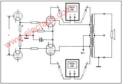
Figure 8 Class A power amplifier level screen flow calibration diagram 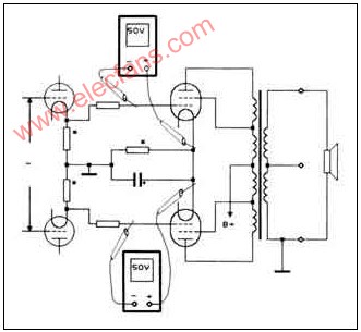
Figure 9 Class AB power amplifier stage gate negative pressure adjustment diagram
After the initial adjustment of the whole machine, connect the negative feedback network between the cathode of the input tube and the output stage. Because the deep negative feedback of the large loop will bring great harm to the transient response of the power amplifier, the electrical performance index of this circuit is not pinned on the large loop negative feedback when designing, but is dedicated to the local negative of the amplifier at all levels Feedback and improve the quality of the amplifier from the direct coupling of the circuit and the output of the cathode.
If there is no abnormal phenomenon in the debugging of the whole machine, the audio signal can be injected from the input end for trial listening. If the audio signals of CD, VCD, DVD, deck, tuner, etc. are injected, the volume control potentiometer is placed in the middle position, and the machine is turned on continuously for about lh, and there is no abnormality in the internal parts of the machine, it can be considered that the initial installation is smooth.
However, during the initial assembly, many problems will inevitably occur, such as hum, noise, distortion and other abnormal phenomena. The following is a brief analysis to eliminate the whole machine failure.
9. Troubleshooting
1. Silent failure
As shown in Figure 10 (a), the fuse blows in the middle. Install a fuse that meets the specifications. If it blows again, it indicates that there is a local short circuit or overcurrent in the machine. 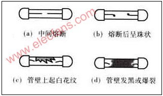
Figure 10 (c) White patterns appear on the tube wall. The power amplifier stage or the power supply part has breakdown and short circuit phenomena, such as the breakdown of the power supply filter capacitor or the previous stage decoupling capacitor, and the poor insulation between the output transformer stages of the power amplifier stage, resulting in local short-circuit between poles.
Finally, the audio signal can be sent to the grid of the power amplifier tube. The amplification of a single power amplifier tube is limited, and it needs a stronger driving power. Therefore, the input audio signal should be strengthened. If it is normal, the speaker can emit lighter. Sounds.
3. Distortion failure
When the input signal is too strong, it will often cause overload distortion of the input stage. Generally, you can turn off the volume potentiometer to solve it. If the output voltage of the CD, VCD and other signal sources used is high, and the volume potentiometer is inconvenient to control, a 1-3kll resistor can be connected in series in the gate loop of the input tube for attenuation.
The quality of the inter-stage coupling capacitor is not good, or there will be distortion when there is leakage, and the inter-stage coupling capacitor with good quality and good quality should be replaced.
In addition, when the output impedance of the power amplifier does not match the impedance of the speaker box, distortion will also occur. If the impedance of the output transformer is too small, the playback sound of the speaker will be sharp; if the impedance is too large, the playback sound will be dull.
The filter capacitor has poor voltage resistance, and flashover may also occur inside. When the quality of the filter resistance of the high-voltage power supply is poor or the power consumption is insufficient, not only the temperature rises, but also the noise.
In addition, the welding quality of the whole machine is not good, when there are false welding and virtual welding between the contacts, there will be noise when the connection is turned on and off.
The inter-electrode flashover in the front-stage tube or the leakage of the bakelite tube lamp holder, etc. can also cause noise.
How to use EL34 to make integrated tube power amplifier
Assembly of power amplifier