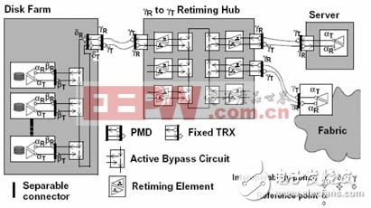
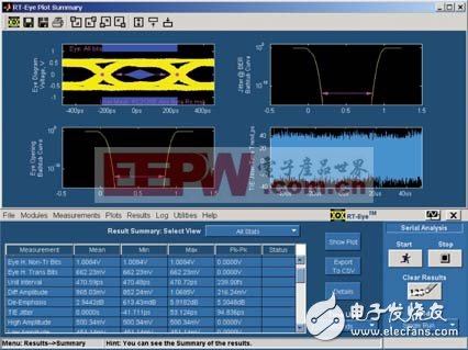
With the advent of third-generation I/O technology, people began to enter the era of high-speed transmission. How to maintain signal integrity is a challenge when using high-speed serial buses such as PCI Express or SATA. This article introduces the basic knowledge and methods of signal integrity verification with examples. In general, the design of electronic products is inseparable from the following parts: power supply, clock, reset signal, bus and interface. It is the signal of each part that connects the whole system and is one of the important roles that determine the stability of the system. . The stability of the system and the quality of the design can be seen from the perspective of the signal itself. In fact, this is the content of signal integrity research. --- With the continuous development of technology, design engineers will increasingly face the problem of design and processing of high-speed signals. The development of high-speed data bus technology has also brought new challenges to testing. --- This article refers to the address: http://TIcle/196100.htm The third-generation I/O technology, PCI Express, enables people to break through the bottleneck limitations of previous PCI bandwidths and design their own high-performance systems more flexibly. For PCI Express testing, PCISIG already has detailed testing methods, but the actual system is very different, PCISIG can not be clearly defined, so it needs to have a deep understanding of the technical characteristics of each bus specification, determine In the end, that is the standard that meets the actual system. Not only PCI Express, but also the measurement of Fibre Channel (Fiber Channel), Infiniband, Gigabit Ethernet, 1394b, USB and other signals have the same problem. --- For any bus or signal test, first of all to be familiar with the technical specifications used, an experienced engineer only need to look at the technical specifications, you can roughly find the test method, of course, you need to configure a complete instrument Only then. --- First look at the measurement of the eye diagram, to test the eye diagram, you must first find the template of the specified eye diagram, which is Eye Mask. Each technical specification will have clear regulations. Engineers can find the specifications of the eye diagram template from the technical specifications. On the test instrument (such as an oscilloscope), edit the eye diagram template according to the specifications. Figure 1 shows the corresponding points of the Fibre Channel standard. Different eye diagram templates. In general, the instrument manufacturer will have the template file that has been prepared, just call it. Of course, the engineer must check the standard. The instrument manufacturer sometimes does not necessarily provide the correct one, which will waste a lot of time for the user. . As for the next test, it is as simple as connecting the test signal to the instrument, or directly to the test point, through a dedicated test fixture, or through an output interface. --- Now the high-speed serial bus with 8B/10B encoding is the trend, as well as pre-emphasis, deemphasis, embedded clock, etc. are more important concepts. --- In the process of testing, how to capture the required signal is a key, such as PCI Express, Fibre Channel and other tests is very simple, it will automatically send out a series of Compliance pattern for testing. But for Ethernet, 1394, etc., it is not so simple, which requires the support of each chip manufacturer, the user needs to get the chip from the chip manufacturer how to open the chip's register, so that the chip enters the so-called test mode (test mode) The desired pattern or package so that you can grab the desired signal and verify its quality. --- When it comes to grabbing signals, of course, you can't do without the instrument probes, but for different technical specifications, there should be different selection requirements, such as bandwidth, rise time, sensitivity, sampling rate, etc. Contact, they will have some solutions, but these basic things need to be mastered by the users, because the price of many test instruments can be very expensive. --- When the engineer grabs the signal, he can test it. Many instrument manufacturers now offer some fool-like applications. Users can complete most of the tests by simply clicking on run or start, and will automatically generate reports. But engineers can't rely too much on instrument manufacturers. Many of these applications are not free, and they are expensive. Second, instrument manufacturers are not omnipotent. Sometimes, some parameters have to be measured one by one. In fact, this is the time to reflect the value of engineers. The following is a brief introduction to the test of Fibre Channel signals as an example. --- The measurement signal is Fibre Channel (FC), and the signal rate is 2.125Gbps. Based on the signal rate, a 7 GHz bandwidth, 20 GSPS sampling rate real-time oscilloscope Tektronix TDS7704B was selected. The probe is a differential probe P7350 with a bandwidth of 5 GHz. Note that the oscilloscope must have a CDR (clock distract recovery) module. Because the clocks of these high-speed serial buses are embedded in the data, the CDR is required to recover the clock signal from the data. In order to sample the signal. Another is real-time serial data analysis software, such as Tektronix RT-eye software. Currently, this software can complete most of the test items of Fibre Channel signals, such as eye diagram, jitter, rise time, fall time, eye height, eye width, Jitter@BER, Dj, Rj, eye opening@BER, rate, UI, and You can draw bathtub curves, charts, histograms, and more. Figure 2 shows the test results of the actual 2.125 GHz Fibre Channel signal, and Figure 3 shows the test results of the 2.5 GHz PCI Express bus signal. --- Here to be reminded are the following points, one is the setting of the pattern length, the second is the choice of pattern type, the third is the choice of the bandwidth of the phase-locked loop filter, and the fourth is the amount of data required by the BER.
Electromagnetic relay is an electronic control device that has a control system (also called an input loop) and a controlled system (also called an output loop). It is usually used in an automatic control circuit, which actually uses a smaller current and is lower. The voltage is an "automatic switch" that controls large currents and higher voltages. Therefore, it plays the role of automatic adjustment, safety protection and conversion circuit in the circuit.
Electromagnetic Relay,MY Series Electromagnetic Relay,Mini Electromagnetic Relay,LY General Electromagnetic Relay Ningbo Bond Industrial Electric Co., Ltd. , https://www.bondelectro.com