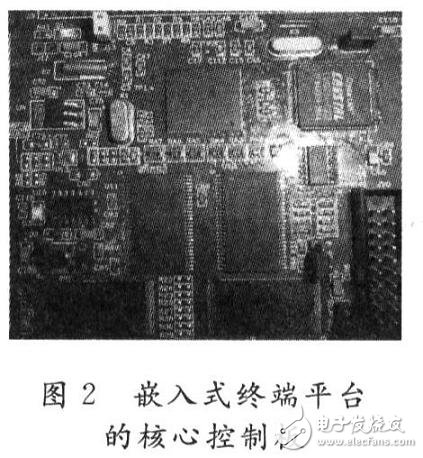
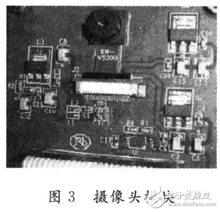
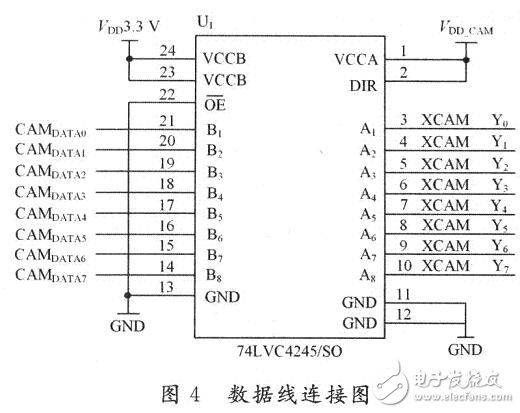
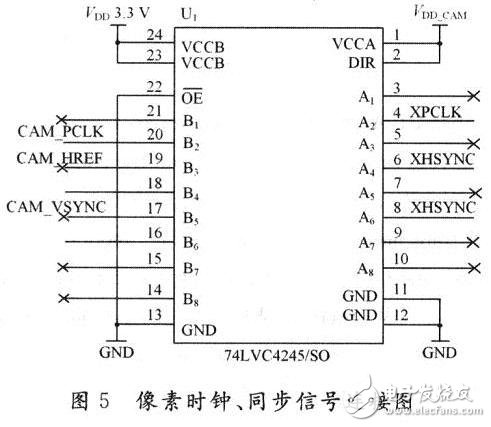
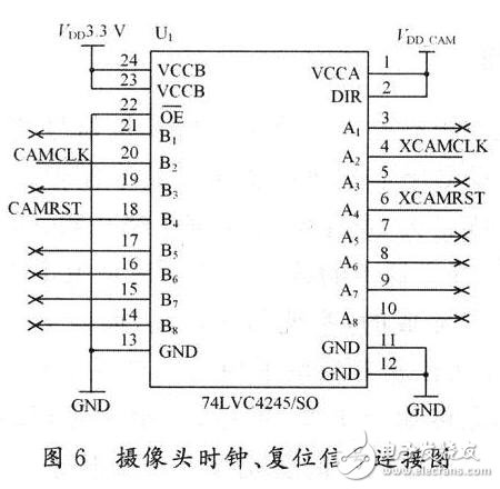
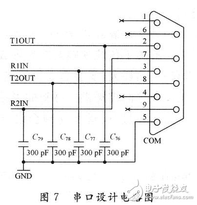
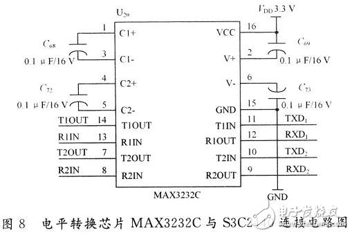
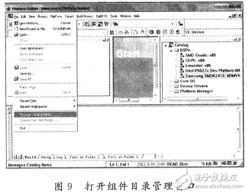
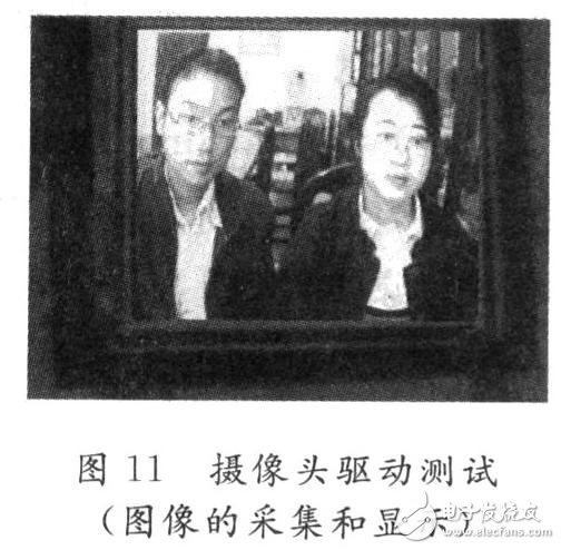
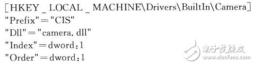
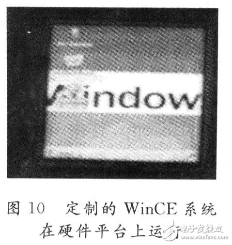
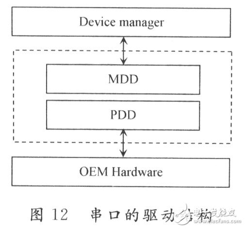
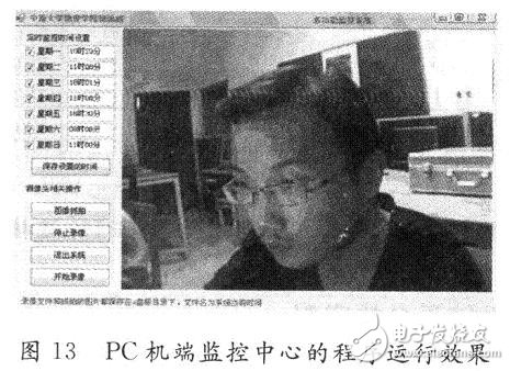
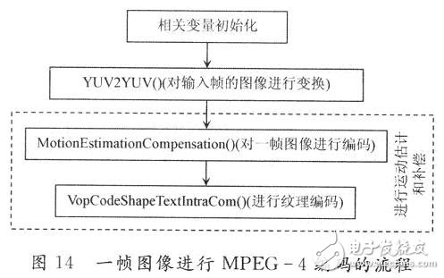
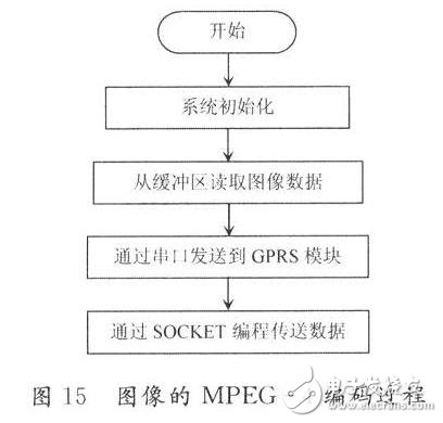
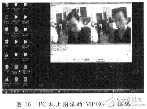
The traditional video surveillance system is mainly based on analog signal monitoring system and card-based digital monitoring system. Among them, the analog signal monitoring system has a large amount of wiring engineering, which consumes a large amount of storage medium, and the query and evidence collection is also very cumbersome; the digital monitoring system based on the card is completed by a PC and an image acquisition card, and the cost of the system is high, and the PC The machine needs to be manned and cannot be used in harsh environments. In the field of video surveillance, how to make information transmission faster, more stable, and farther away, the system's cost, size, and lower power consumption are the top issues facing current technology developers. A wireless video surveillance system based on embedded Windows CE5.O is proposed here. The invention solves the problems of high cost, large volume, limited transmission distance, large power consumption and inconvenient installation of the traditional video monitoring system. The design of the system will provide a new way of thinking, method and technical route for wireless video surveillance; it has broad application prospects in the fields of security, distance education, remote video conferencing, medical systems and other wireless video. 1 Introduction to the overall hardware block diagram of the system The hardware system of the wireless monitoring system based on embedded WinCE5.0 is mainly composed of embedded terminal and PC on the server side. The microprocessor of the embedded terminal platform selects the S3C2440 based on the ARM9T20 core. The S3C2440 has a rich interface, in which the camera interface is connected with the CMOS camera, the serial port is connected with the GPRS transmitting module, and the server end is mainly a PC and GPRS receiving. Module. The entire block diagram is shown as 1. The system firstly controls the CMOS camera to collect image data through the S3C2440 microprocessor. After compression encoding, the compressed data is transmitted through the GPRS wireless transmitting module. The PC at the server receives the data through the GPRS receiving module and passes the corresponding application. The program decodes the video data and displays it on the screen. The core control board of the embedded terminal platform including the S3C2440 microprocessor is shown in Figure 2. 2 system expansion interface design 2.1 camera interface design The image acquisition chip used in the camera is the OV9650 image sensor, which has a 10-bit data interface and a standard SCCB interface, and is packaged in a CSP-28 package. The chip supports RGB (4:2:2), YUV (4:2:2), YCrCb (4:2:2) three data output formats, built-in 138 device control registers, the address is from Ox00 ~ Ox8A, through The SCCB interface can easily set parameters such as sensor window size, gain, white balance correction, exposure control, saturation, and hue. The camera module containing the image sensor OV9650 is shown in Figure 3. The S3C2440 has a dedicated camera interface. The CPU can be directly connected to the CMOS image sensor. When the 0V9650 output data format is 8-bit YUV, the data lines D2 to D9 (D9 is the MSB bit and D2 is the LSB bit). The output data format is 10-bit RGB, with data lines D0 to D9 (D9 is MSB bit, D0 is LSB bit), and the system uses YUV format. The camera module is connected to the Camera interface of the S3C2440, and the circuit diagrams thereof are shown in Figures 4-6. TI's level-shifting chip 74LVC4245 is used, which is a dual-power level shifter in which level shifting is performed. 5 V uses 5 V as the VDD_CAM, and 3.3 V uses 3.3 V as the VCC33. Dual power supply ensures that the output swing of both ports can reach the full power supply amplitude. 2.2 GPRS module interface design The S3C2440 has three UART channels. One of the channels is designed to be connected to the GPRS module. The S3C2440's own UART controller makes hardware development and software design simple. However, the high and low level signals defined by the RS 232 standard are completely different from the high and low level signals defined by the circuits of the general microcontroller system. For example, the standard logic "1" of the S3C2440 system corresponds to the level 2 to 3. V, the standard logic "O" corresponds to a 0 to 4 V level. Obviously, it is completely different from the level signal described in the RS 232 standard. To communicate between the two, the signal level must be converted. Currently used level conversion chips are MAX232, MAX3221 and MAX324.3. The specific design circuit is shown in Figure 7 and Figure 8. 3 customization of the operating system platform Windows CE is a highly modular embedded operating system. Because of this, users customize the operating system to meet specific requirements. If you customize the Windows CE operating system for your embedded device, you must create, build, and run it. And a series of operations such as releasing the OS. In the wireless video surveillance system, according to the functional requirements, the process of customizing the system using Platform Builder 5.0 is as follows: (1) Import the BSP development kit. Since the Samsung S3C2440 based on the ARM920T core is used, the SMDK2440.CEC file under the SMDK2440 file is found in the BSP package and imported. Open "Platform Builder5.0" and select "Manage Catalog Features" under the "File" menu, as shown in Figure 9. In the dialog box that is displayed, click Import. Browse to the smdk2440.cec file in the SMDK2440 file and import it. (2) Create a project. According to the requirements of the WinCE wireless monitoring system, select the appropriate components to implement in the process of customizing the system. Among the components are: MFC components that support application development and related components that support the network. (3) Compile the project: Click the menu "Build OS" → "Sysgen" to start compiling the project. (4) Download the runtime image and start it after successful debugging. After successful compilation, files such as nk.bin and nk.nb0 will be generated under WinCES00\PBWorkspacesestl\RelDir\smdk2 440_ARMV4I_Release, and nk.nb0 will be downloaded to the hardware platform for running. 4 driver development 4.1 Camera driver development Camera driver development is a difficult and a key part of the design. Since the video data captured by the camera can be processed as a data stream, the driver for the camera will be developed using a streaming interface. (1) Open the previously customized operating system project in Platform Builder, and then create a new WIN32 DLL project, add 2 C++ source files, namely: camera.cpp and IIc.cpp, where camera-a.cpp contains drivers. The entry function DLLMain(); the prefix of the driver is "CIS", and IIc.cpp contains functions for configuring the camera-related registers through the ICC interface. (2) According to the previous hardware circuit and the working sequence of the OV9650 chip, the OV9650 is initialized by writing the CIS_Init function of the stream interface. It mainly includes the following three steps: calling InterrupTIniTIalize(SYSINTR_CAM, CameraEvent, NULL, 0) function to notify the system to register the interrupt; calling CreateEvent() to create a CameraEvent event; calling CreateThread() to create the CameraThread thread. Call the WaitForSingleObject(CameraEvent, Dis-play TIme) function in the Camera Capture Thread service function to wait for the Camera Event event to occur. This event is triggered by the SYSINTR_CAM interrupt associated with it. In addition, other stream interface functions (CIS_IOControl, etc.) can also be implemented in a similar way. (3) Write the DLL's export function definition file .DEF. The .DEF file defines the exported function class table for the DLL. The .DEF file can be edited with a normal Notepad. When saving, the suffix name can be changed to .DEF. The contents of the .DEF file for this camera driver are as follows: (4) Configure the registry for the driver. Add the following registrations to platform.reg: After the camera driver development is completed, the application is written on the touch screen of the embedded terminal, as shown in FIG. First, create a form for displaying images through the CreateWindow API function, and then create a thread of the callback function CaptureThreadProc. In the callback function, different message values ​​are sent to the operating system according to different operations, and the image is read and displayed. The test results are shown in Figure 11. 4.2 Serial Port Driver Development In Windows CE, the driver implementation of the serial port has a fixed model, based on the stream drive model, and adopts a hierarchical structure. The development steps of the serial port driver are the same as the steps of the above camera driver development. The key is to implement the stream interface function. Since the layered structure is adopted here, the code of the MDD layer can refer to the source code provided by Microsoft at %WINCEROOT%\PUBUC\COMMON. In the \OAK\DRIVERS\SERIAL\COMMDD2 directory, the code in the PDD layer is hardware-related code that needs to be written for different devices. The code in the MDD layer calls the code in the PDD layer to implement specific hardware operations. The structure of the serial port driver is shown in Figure 12. 5 PC terminal monitoring center program development The monitoring center is the core part of the wireless video surveillance system, which is responsible for managing the entire system and displaying the monitored images. In this paper, the application of the monitoring center realizes real-time monitoring, timing recording, and snapping. The development of the monitoring program in the system, using the C# language and WIN32 API, using the C# language event-based programming method, designed the program graphical interface, using the API function in the VFW interface to design the underlying image data based on the message mechanism. And display. The API functions in this system are mainly from the VFW software toolkit. VFW (Video for Windows) provides a series of application programming interfaces (APIs) that allow users to easily implement common functions such as video capture, video editing and video playback, as well as callback functions to develop more complex video applications. Its feature is that when playing video, there is no need for dedicated hardware devices, and the application is flexible, which can meet the needs of video application development. The effect of the program debugging operation of the monitoring center is shown in Figure 13. 6 Video compression coding and transmission theory research 6.1 Video compression coding research Images and video contain a huge amount of information, which requires a very wide bandwidth for transmission and storage. Multimedia video data must be compressed before it can be transmitted wirelessly. Commonly used digital compression technologies mainly include H.261 compression coding for conference television systems, JPEG for computer still image compression, MPEG digital compression technology for moving image compression, and H.263 and H. 264 compression coding technology. MPEG-4 adopts a new generation of video coding technology, which extends the coding object from image frames to practically arbitrarily shaped video objects for the first time in the history of video coding, thus implementing pixel-based traditional coding to object-based and content-based content. The transformation of modern coding has led to the development of a new generation of intelligent image coding. Due to the complexity of the MPEG-4 compression coding system, the MPEG-4 compression coding technology will be studied in the paper, and the source code of the compression coding on the PC will be analyzed, which will lay a foundation for the future transplantation on ARM and other embedded devices. The flow of performing MlPEG-4 encoding on one frame of image is as shown in FIG. Compiling the source code of the open source MPEG-4 XVID model will generate an xvidcore.dIl file, and call the relevant functions in the library in the application development. The program execution process is shown in Figure 15. The program is tested on a PC, first reading the video data from the camera, and then performing MPEG-4 encoding. 6.2 Wireless Transmission Research GPRS adopts wireless IP technology based on packet transmission mode to transmit data at high speed in an efficient manner. It supports the most widely used IP protocol and X.25 protocol on the Internet, and the transmission rate is up to 117 KB/s, so video data passes MPEG. After a 4 compression, it can be transmitted through the GPRS module. In this transmission process, connection establishment and data transmission of communication are implemented through the API of the TCP/IP network and the Socket interface. The overall wireless transmission effect is shown in Figure 16. 7 Conclusion The wireless monitoring system based on Windows CE5.0 involves many aspects of computer programming technology, embedded technology, video coding, wireless transmission, etc., and a lot of work has been done in this subject, and the test results have achieved the intended purpose of the paper. The embedded terminal platform has the characteristics of small size, low power consumption, fast running speed, clear image collection, etc. The design of the monitoring center program also has a friendly human-computer interaction interface, which realizes functions such as timing monitoring, video recording and photographing. In terms of video compression and wireless transmission, the feasibility of the theoretical research method is proposed, and a specific solution is proposed, which lays a solid foundation for further perfecting the system in the future.
This 48 port USB charging station is used for the safe charging of iPhoneX, Samsung, Xiaomi, Huawei, laptop, tablet and other equipment. Portable -with a mini version of the family size desktop charger, plus compact size and lightweight weight make multiple USB charger stations very suitable for travel. Automatically detect and secure -automatically identify and adjust the best charging speed of the device. It will always collect it in the fastest and safest way. The USB charger has high current, charging and short -circuit protection, which can extend the battery life of the equipment. Environmental protection -compatibility, charging objects are not restricted, avoid using multiple chargers. Spend AC to USB data cables to USB charging sockets to meet the charging device. To MP3, MP4, DV, Bluetooth -free, all kinds of mobile phones, digital cameras and other digital products all 5V power supply costs.
48 Port Type-C Charger,Multiport Usb Charger,Usb Wall Charger Power Hub,48 Ports Usb Charging Station shenzhen ns-idae technology co.,ltd , https://www.szbestchargers.com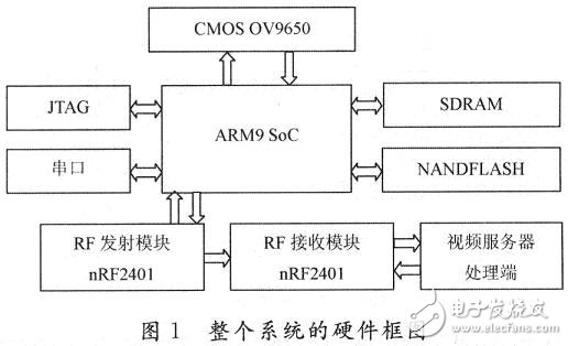

Design and Application of Wireless Video Surveillance System Based on Embedded Windows CE5.O
48 Ports usb charging station